Page 74
3 Specifications of the Devices
I
2
C System Bus
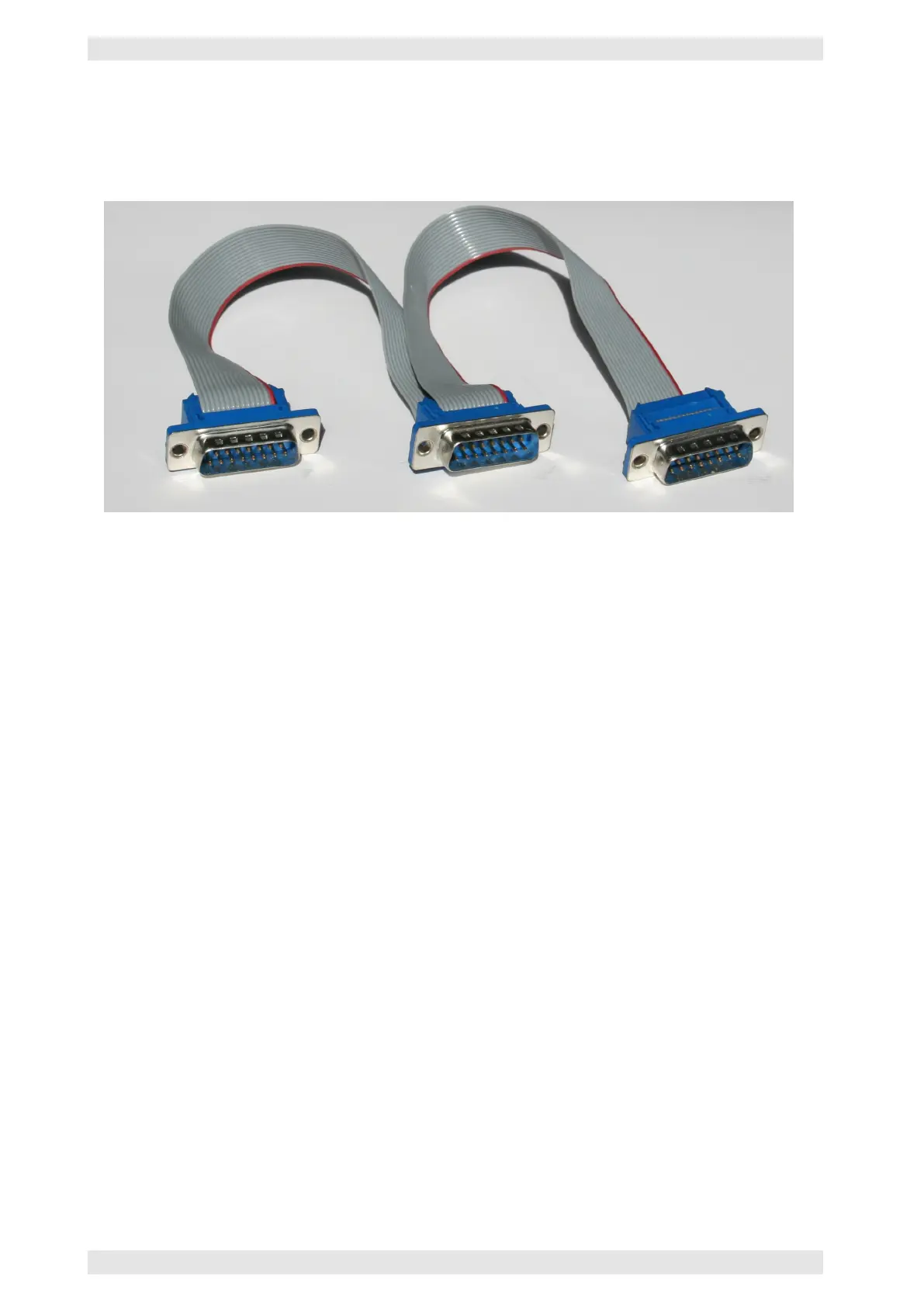
The units are connected with a 15-pin ribbon cable. It is equipped with male Sub-D DB–15 connectors. One
connector is required for each amplifier, the AX16 and the SXL II.
Figure 3.58: SXL II - I
2
C System Bus Cable
The I
2
C system bus transmits the following signals:
• Control signals in I
2
C format (refer to section 2.11.1)
• Audio of the emergency paging bus (only XR Series, see section 3.5.6)
• Audio of the monitor bus (only XR Series, siehe section 3.5.6)
• 12V supply voltage for the interface boards of the amplifiers and the AX16 (see section 2.11.1)
The maximum cable length is 2 meters. The devices need to be installed in such a way as to not exceed the
maximum cable length.
Preassembled cables or ribbon cables and single connectors may be ordered from your supplier.
RS–485 System Bus
An „off the shelf“ CAT5 patch cable may be used.
For the pin layout of the RS–485 connector please refer to section 2.11.2.
3.14.4.3 Address IDs
A unique ID needs to be assigned to every amplifier that is connected to an SXL II via the system bus. It may
be set via the DIP switch on the backside of the amplifier.
Every two channels of an amplifier share one ID. Consequently, every two-channel amplifier uses one ID,
four-channel amplifiers two IDs and eight-channel amplifiers four IDs. The table explains the different
settings.
c
2016 Bittner Audio Int. GmbH