3 Specifications of the Devices
Page 63
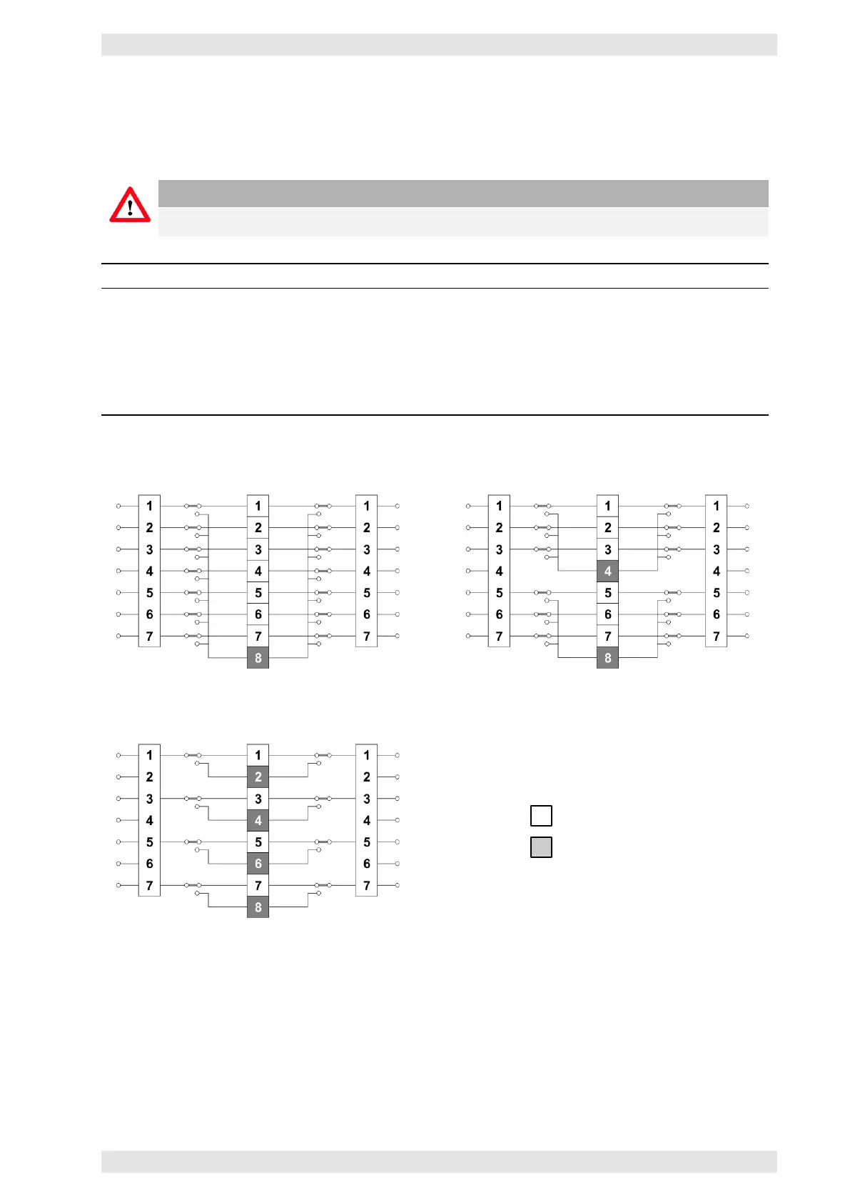
3.13.5.1 Switching Modes
The switching modes determine how many amplifier channels are being backed up. The switching modes
are selected with DIP switches 1 and 2 of the block SW3 on the rear panel of the device.
Caution
To activate the DIP-Switch SW3 settings the AX16 has to be re-powered.
Mode 7+1 Mode 3+1 Mode 1+1
Eight amplifiers (16 channels)
may be connected. Seven
amplifiers (14 channels) are being
used as program amplifiers and
one amplifier (2 channels) as the
backup amplifier.
Two groups of four amplifiers (8
channels) each may be
connected. Three amplifiers (6
channels) of each group are
being used as program amplifiers
and one amplifier (2 channels) as
the backup amplifier.
Four groups of two amplifiers (4
channels) each may be connected.
One amplifier (2 channels) is
being used as program amplifier
and one amplifier (2 channels) is
being used as the backup
amplifier.
Mode 7+1
Mode 3+1
Mode 1+1
Program Amp
Backup Amp
Figure 3.43: AX16 - Switching Modes
3.13.5.2 Connected Amplifiers
The DIP switches 1 to 8 of block SW1 tell the AX16 whether an amplifier is connected or not.
• ON: amplifier is connected
• OFF: no amplifier is connected or the amplifier is controlled by an SXL II (refer to Split Mode sec-
tion 3.14.9.5).
c
2016 Bittner Audio Int. GmbH