Page 12
2 Technical Features
2.4 LED Indicators
2.4.1 Frontside
The amplifiers are equipped with 4 LEDs for each amplifier channel:
LED Color Function
POWER green The amplifier is powered up.
CLIP red The input is overloaded. The LED starts illuminating as soon as the signal is 0.5 dB
under full power.
SIGNAL green The signal reaches the output stage of the amplifier.
PROTECT red This LED will light up as soon a protection circuit has been activated or if one of the
output relays has been activated. When the amplifier is switched on, this LED will
light up for approximately 1.5 seconds.
The amplifiers of the XB and XV Series feature an Overheat LED on the front panel. If the amplifier reaches
an operational temperature of 90
◦
Celsius the LED will light up.
The amplifiers of the XV DC and 4DXV Series are equipped with 2 additional LEDs on the front panel for the
supply voltages:
LED Color Function
AC POWER green Mains is present
DC POWER green Backup Power +24V is present
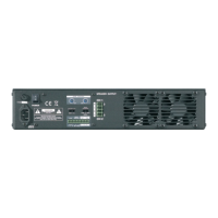
2.4.2 Backside
Amplifiers with an incorporated micro controller use an LED to indicate its operational status:
• slow blinking (about 1x/sec): All channels are OK
• fast blinking (about 3x/sec): Either the power supply failed or at least one of channels is in protect
Caution
After a power on of the amplifier the LED is blinking fast (up to 3 sec.) until all internal supply
voltages have reached their correct levels.
Figure 2.3: Amp Status
2.5 Level Control
2.5.1 Analog Level Control
The amplifiers are equipped with two analog level control knobs, which are setting the level of the amplifier.
The adjusting range is –90dB to 0dB. The 16 different settings of the switch are as follows:
c
2016 Bittner Audio Int. GmbH