Page 64
3 Specifications of the Devices
3.13.5.3 Logic of Alive Contact
The DIP switches 1 to 8 of block SW2 determine the control logic of the connected alive contacts in case of
a failure:
• ON: positive logic (contact open if amp fails)
• OFF: negative logic (contact closed if amp fails)
Caution
If the AX16 is connected to an SXL II, these DIP switches are disabled for every amplifier, which
is also connected via its data port to the SXL II (refer to Split Mode section 3.14.9.5).
3.13.5.4 Control Modes
The backup switching may be activated in two different ways, which are selected by DIP switch 3 of block
SW3:
• ON: Control by a connected SXL II
• OFF: Control by the ALIVE contacts of the connected amplifiers or any other potential-free contact
Caution
In case of using contact closures and the SXL II (refer to Split Mode section 3.14.9.5), the DIP
switch has to be set to ON.
When using the contact inputs, a single contact will control one amplifier (2 channels). This contact is
directly compatible with the ALIVE (fault detection) contacts of Bittner Audio amplifiers.
In addition, any other potential-free contact may be used. The switching will take place after the contact
has been activated (amplifier defect will be indicated by either an opened or a closed contact). This logic
operation (positive-negative) needs to be set with DIP Switch block SW 2 for each amplifier.
3.13.6 Connection of Amplifiers
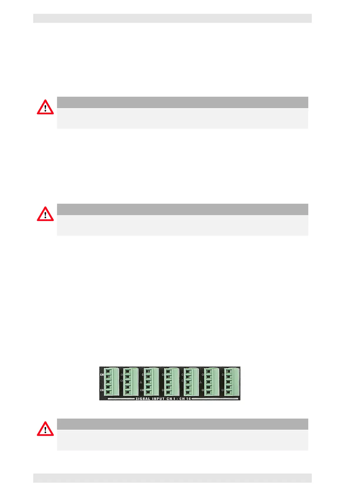
3.13.6.1 Signal and Amplifier Inputs
The signal inputs of the individual channels may be connected to the PHOENIX terminals Signal Input CH1
– CH14.
Figure 3.44: AX16 - Signal Inputs
Caution
Since the backup amplifier does not have its own input, only 14 inputs are needed on the AX16.
The input signal of the backup amplifier is made up of the input channels of the faulty amplifier.
c
2016 Bittner Audio Int. GmbH