BASE Module Part B VC-6000
TM
Compact monitor
© VC-6000
TM
Compact monitor Nov, 2014 C100584.002 Module Vers. 08 - 9 -
1.4 The connections – their function and layout
1.4.1 Sensor Interface Module: Connections X1, X2 and X3
The socket positions X1_M, X2_M and X3_M belong to the connections X1
to X3.
These socket positions can be equipped with Sensor Interface Modules or
the 2-channel conditioner module for BCU.
The input modules for sensors receive the input signals from the sensors at
the connections associated with the appropriate socket positions.
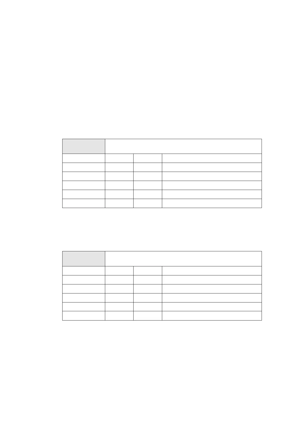
A-TIM (-24 V): Connection layout for 1-channel input module for
AS- sensor (e.g. AS-022, AS-030)
Connection
X1/X2/X3
A-TIM (-24 V)
Pin 1 0 V OUT Sensor power
Pin 2 -24 V OUT Sensor power
Pin 3 COM IN signal in (common)
Pin 4 SIG IN signal in (signal)
Pin 5 does not use
Pin 6 0 V OUT not occupied
A-TIM-CCS*: Connection layout for 1-channel input module for
AS- sensor (e.g. AS-062, 8325, 8327)
∗ CCS = constant current supply
Connection
X1/X2/X3
A-TIM (CCS)
Pin 1 0 V OUT not occupied
Pin 2 -24 V OUT not occupied
Pin 3 COM IN signal in (common)
Pin 4 SIG IN signal in (signal + 8 mA current out)
Pin 5 does not use
Pin 6 0 V OUT not occupied