BASE Module Part B VC-6000
TM
Compact monitor
© VC-6000
TM
Compact monitor Nov, 2014 C100584.002 Module Vers. 08 - 11 -
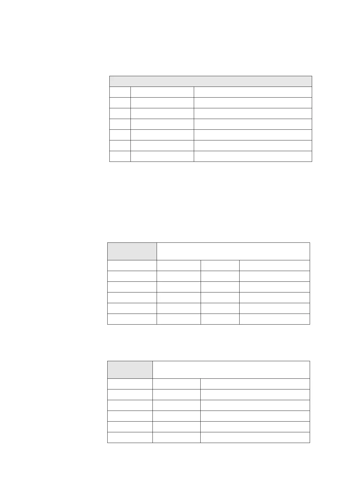
BINARY-IN: Connection layout for 3-channel input module for
binary status signals
BINARY-IN Pin-connection layout (X1 –X3)X4 to X9
PIN Signal Explanation
1 HI A Channel A input SIG (HIGH)
2 LO A Channel A input GND (LOW)
3 HI B Channel B input SIG (HIGH)
4 LO B Channel B input GND (LOW)
5 HI C Channel C input SIG (HIGH)
6 LO C Channel C input GND (LOW)
1.4.2 Output and supplementary modules: Connections X4 to X9
The socket positions X4_M to X9_M belong to the connections X4 to X9.
These socket positions can be equipped with Output modules (Relay and
DC out). The connection layout is dependent on the equipped module type.
DC-OUT (2-ch.): Connection layout for 2-channel output module
for current/voltage
Connection
X4 to X9
DC-OUT (2ch.)
Pin 1 Volt In A OUT Voltage, channel A
Pin 2 Curr In A OUT Current, channel A
Pin 3 COM A OUT Common, channel A
Pin 4 Volt In B OUT Voltage, channel B
Pin 5 Curr In B OUT Current, channel B
Pin 6 COM B OUT Common, channel B
RELAY-OUT (2-ch.): Connection layout for 2-channel Relay out-
put module
Connection
X4 to X9
RELAY-OUT (2ch.)
Pin layout in the de-energised condition
Pin 1 ARM RelA Arm, Relay A
Pin 2 NO RelA Normally-open contact, Relay A
Pin 3 NC RelA Normally-closed contact, Relay A
Pin 4 ARM RelB Arm, Relay B
Pin 5 NO RelB Normally-open contact, Relay B
Pin 6 NC RelB Normally-closed contact, Relay B