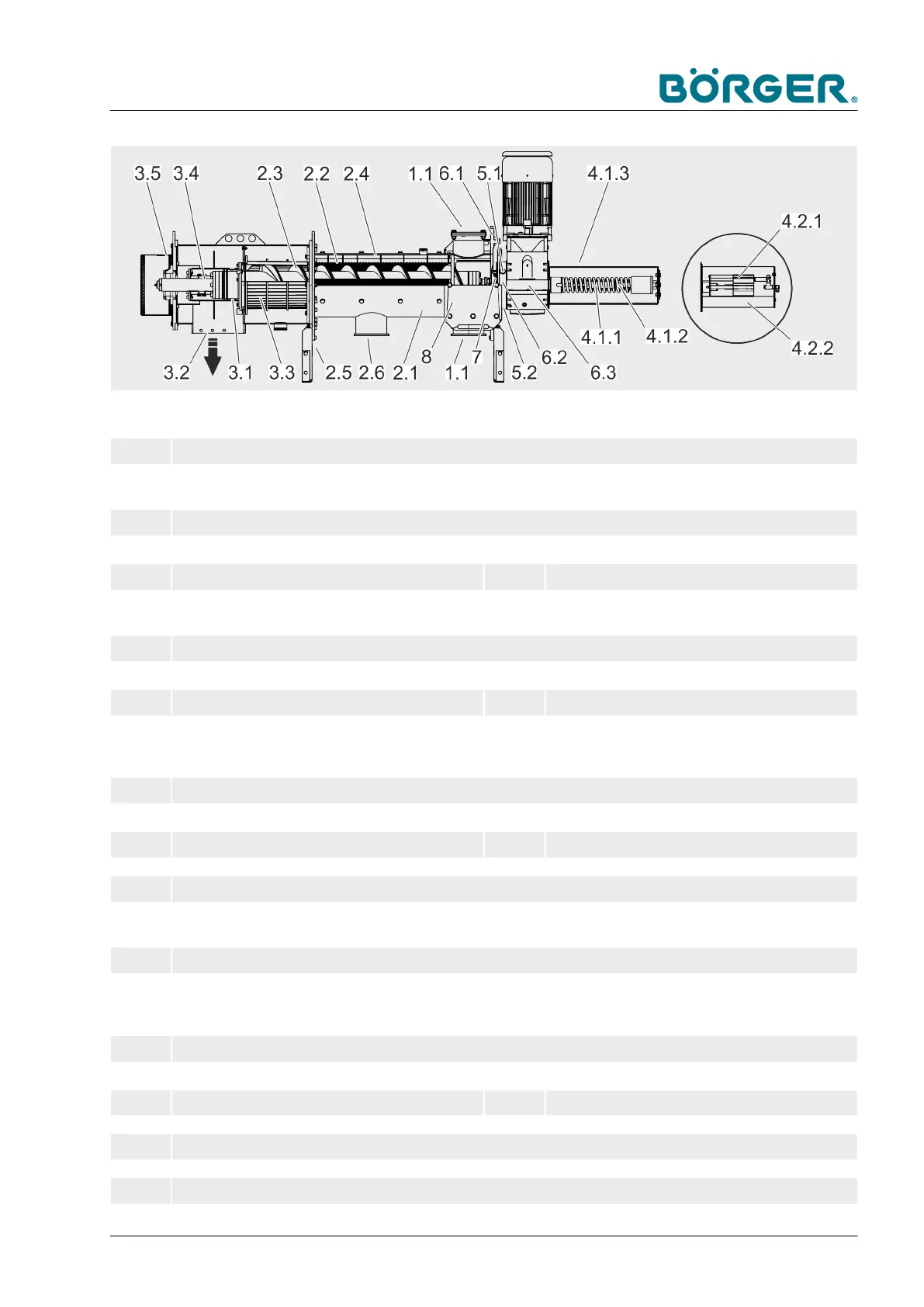
1 Feed unit
1.1 Inlet (substrate)
2 Separating and conveying unit
2.1 Pipe casing 2.4 Rotation lock on screen
2.2 Wedge wire screen 2.5 Mounting rail
2.3 Brush auger 2.6 Outlet (liquid phase)
3 Compactor unit
3.1 Multi Disc (sealer/peeler) 3.4 Adjustment mechanism
3.2 Counter bearing casing 3.5 Counter bearing cover
3.3 Press channel or filter press channel for HP ver-
sion
4.1 Easy Shift clamping unit - mechanical
4.1.1 Tension springs 4.1.3 Cover of mechanical clamping unit
4.1.2 Clamping screw
4.2 Easy Shift clamping unit - pneumatic
4.2.1 Pneumatic cylinder 4.2.2 Cover of pneumatic clamping unit
5 Intermediate chamber (quench)
5.1 Filler for quench fluid, safety opening with safety
plug
5.2 Drain for quench fluid
6 Drive connection
6.1 Motor plate 6.3 Drive shaft
6.2 B5 flange
7 Shaft seal, mechanical seal
8 Maintenance opening
Product Description
BA-RC40_EN, 17.01.2024 www.boerger.de / www.boerger.com 45