4.4.6 Connection of pneumatic unit
CAUTION!
Risk of injury due to residual pressure!
Residual pressures may still be present despite pressure relief.
— Take extra care when removing the compressed air connec-
tions to prevent accidents caused by the release of residual
pressure.
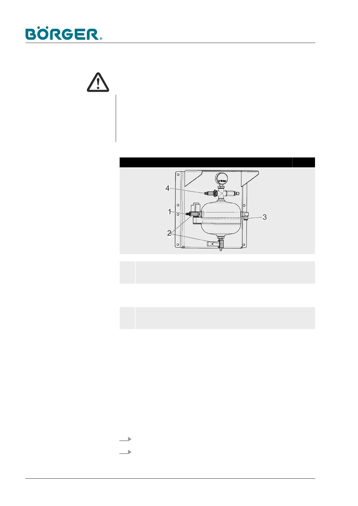
Pressure cylinder of pneumatic unit
1
COMPRESSED AIR SUPPLY
— Coupling connector DN 7.2
2
VALVE
— Valve (MS 18310 24V)
3
PLUG CONNECTION TO THE SEPARATOR
— Plug connection 12mm
4
SENSOR
— PT5404
Be sure to read and follow all instructions:
— on safety,
— on operation and control,
— on installation, repairs and maintenance.
Ä
Chapter 2.12
“Safety instructions for maintenance and rectifying malfunc-
tions” on page 37
1. Connect the plug connection (3) to the separator.
2. Connect the compressed air supply (1) to your compressor.
Transportation, Storage and Installation
BA-RC40_EN, 17.01.2024www.boerger.de / www.boerger.com86