Modular Fire Panel Planning | en 29
Bosch Sicherheitssysteme GmbH System Description F.01U.028.089 | 8.0 | 2011.07
Loop Topology
– In loop topology, the CAN cable is always routed from a CAN1 terminal to a CAN2
terminal [CAN1 ⇒ CAN2].
A CAN segment thus consists of two bus users. The cable length depends on the cable
cross-section.
– Due to the maximum of 32 nodes and the maximum cable length of 1000 m between
nodes, a system can be installed with a total cable length of 32 km.
Networking Panels and Remote Keypads
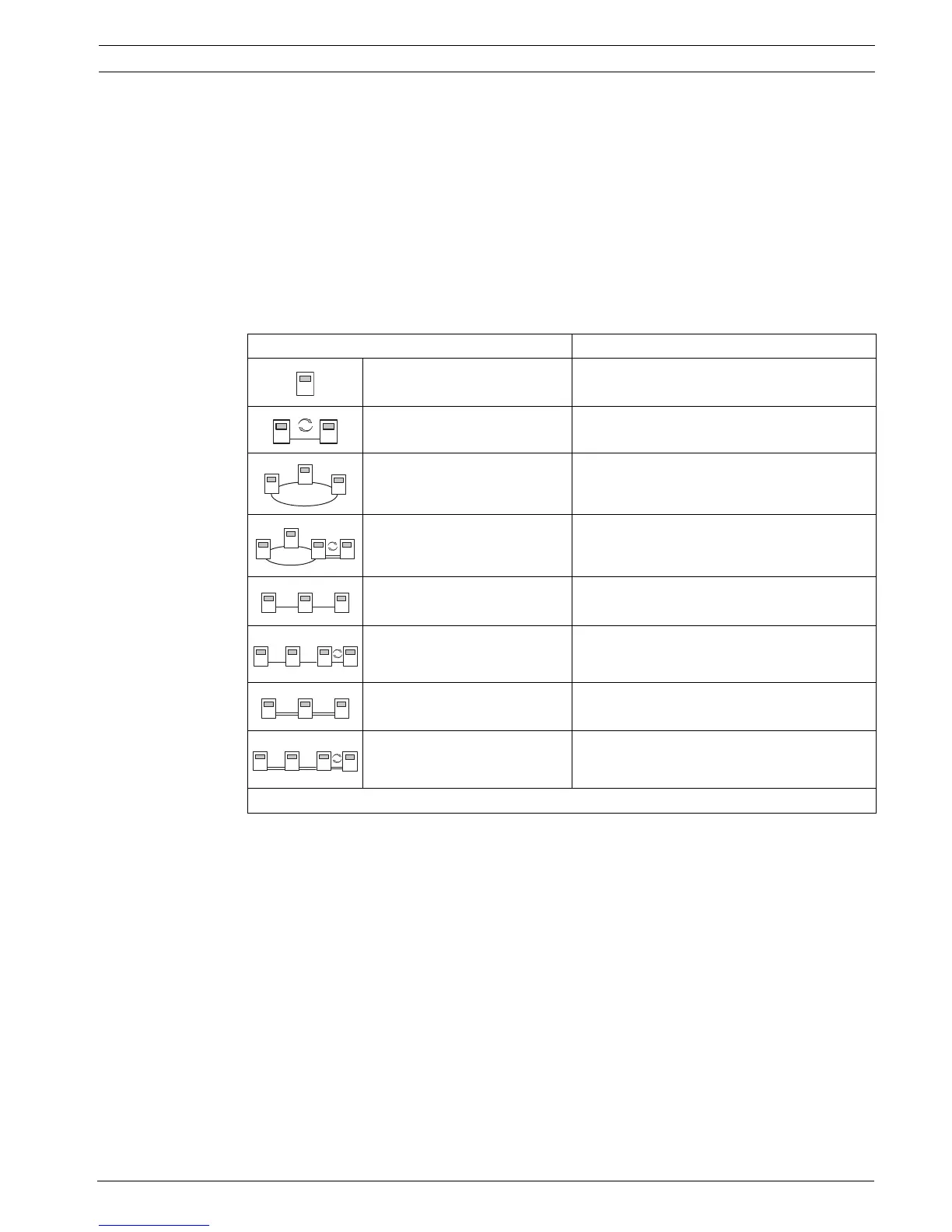
The table below shows the options for networking panels/remote keypads depending on the
network topology.
Table 3.1
Limits in Network
The number of panels and remote keypads that can be networked depends on the choice of
network topology.
Networked panels and remote keypads are known as "nodes".
– The number of detection points in a network is limited to 32,512.
– The number of detection points per panel operated in a network is limited to 2032.
– The number of nodes per system depends on the type of topology.
A node is either an MPC Panel Controller or an FMR-5000 Remote Keypad.
– The number of nodes in loop topology is limited to 32.
– The number of nodes per CAN segment is limited to eight.
A CAN segment is the physical connection of a CAN line.
– The number of nodes in bus topology is limited to eight, whether redundant or not.
In bus topology, there is one CAN segment if not redundant and two CAN segments if
redundant. Consequently, each panel is physically connected to each CAN segment.
Topology Remark
Standalone panel
Standalone panel, redundant
Loop Max. 32 FPA-5000/FMR-5000
Loop with redundant panel Max. 32 FPA-5000/FMR-5000 + 1 redundant
FPA-5000 each
Bus Max. 8 FPA-5000/FMR-5000
Bus with redundant panel Max. 8 FPA-5000/FMR-5000 + 1 redundant
FPA-5000 each
Redundant bus Max. 8 FPA-5000/FMR-5000
Redundant bus with
redundant panel
Max. 8 FPA-5000/FMR-5000 + 1 redundant
FPA-5000 each
Refer to the limits determined by the network topology.

 Loading...


