2. Introduction to the Hardware (Undefined variable: MyVariables.ProductName)
System Description and Overview Part Number: PF40-DI-00010 Rev. A
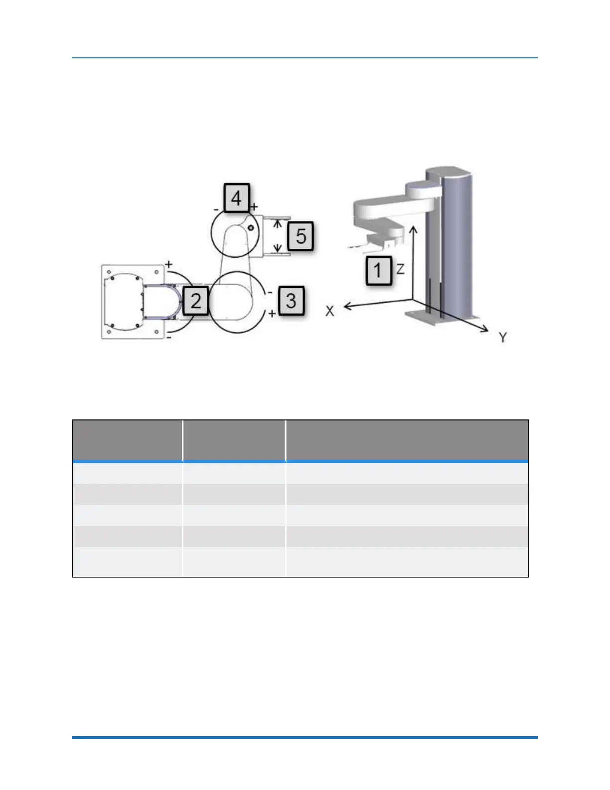
System Diagram and Coordinate Systems
The major elements of the PreciseFlex robot and the orientation and origin of its World Cartesian
coordinate system are shown in Figure 2-1 and defined in Table 2-1.
Figure 2-1: Major Elements of Robot, World Cartesian Coordinate System Orientation & Origin
Annotation Axis Description of Motion
1.
Z column Moves up and down 400 mm
2.
Shoulder Rotates 180°
3.
Elbow Rotates 334°
4.
Wrist Rotates +/- 970°
5.
Gripper
Opens from 77 mm to 133 mm.
Force 0 to 20 N
Table 2-1: Robot Components
The first axis of the robot, J1, moves the robot arm up along the Z Column, which is the Z-axis.
When inner link is closest to the bottom, the Z-axis is at its 0 position in the Joint Coordinate system
and Z=30 mm in the World Coordinate system. As the robot arm moves upwards, both its joint
position and the World Z Coordinate increase in value.
13
Copyright © 2023, Brooks Automation