Brooks Automation 4. Installation Information
Part Number: PF40-DI-00010 Rev. A Accessing the Robot Controller
Accessing the Robot Controller
Although most of the controller interface signals are exposed on the Facilities Panel at the base,
there are times when it may be necessary to access either the robot’s controller or its power
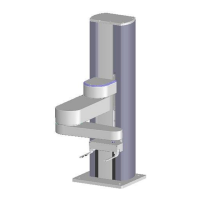
supplies. To access the robot controller, the cover on the inner link must be removed by removing
(4) M3 X 20 SHCS from the bottom of the inner link
See the Guidance 1000A/B Controller, Hardware Introduction and Reference Manual for detailed
information on hardware configuration and interfacing the controller using the various input and
output ports such as those for digital I/O.Also, refer to the Guidance System Setup and Operation
Quick Start Guide for information on configuring the PC and instructions on operating the robot.
Both manuals are available in PDF format and are also contained in the PreciseFlex Library.
Power Requirements
The PreciseFlex 400 power supplies have an input range of 100 to 240 VAC, +/- 10%, 50/60 Hz.
The robots are equipped with an IEC electrical socket that accepts country specific electrical cords.
Power requirements vary with the robot duty cycle, but do not exceed 200 Watts RMS.
Emergency Stop
It is necessary to wire an Emergency Stop Button to the controller. This button may be wired in
series with other emergency stop contacts. The E-Stop signals are available in the green Phoenix
E-Stop connector and the Manual Control Pendant 9-pin DSub connector that is mounted on the
Facilities Panel. See Hardware Reference for detailed information on the E-Stop signals.
Copyright © 2023, Brooks Automation
46

 Loading...