5. Hardware Reference (Undefined variable: MyVariables.ProductName)
System Schematics Part Number: PF40-DI-00010 Rev. A
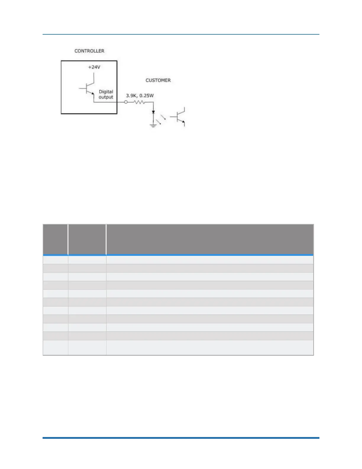
Figure 5-26: Sourcing Digital Output
Outputs can be individually configured as sinking or sourcing signals. For more information on
configuring the jumpers, see the Guidance Controller, Hardware Introduction and Reference
Manual.
The pin out for the G1400B Digital Input and Output Connector and the corresponding GPL signal
numbers are described in Table 5-3.
Pin
GPL
Signal
Number
Description
1 13 Digital Output 1
2 14 Digital Output 2
3 15 Digital Output 3
4 16 Digital Output 4
5 GND
6 24 VDC output
7 10001 Digital Input 1
8 10002 Digital Input 2
9 10003 Digital Input 3
10 10004 Digital Input 4
User Plug
Part No
AMP 1658622-1 or Molex 22-55-2101 or 90142-0010. For the Molex plug, use Molex
sockets 16-02-0103 or 90119-2110 and Molex crimp tool 63811-1000.
Table 5-3: Pin Out for G1400B Digital Input & Output Connector, GPL Signal Numbers
Gripper Controller Digital Inputs and Outputs
If the robot is equipped with an electric gripper, the gripper controller includes three sinking digital
inputs and three sourcing digital outputs. One digital input and one digital output are dedicated for a
71
Copyright © 2023, Brooks Automation