6. Software Reference (Undefined variable: MyVariables.ProductName)
Controlling the PreciseFlex Servo Grip-
pers
Part Number: PF40-DI-00010 Rev. A
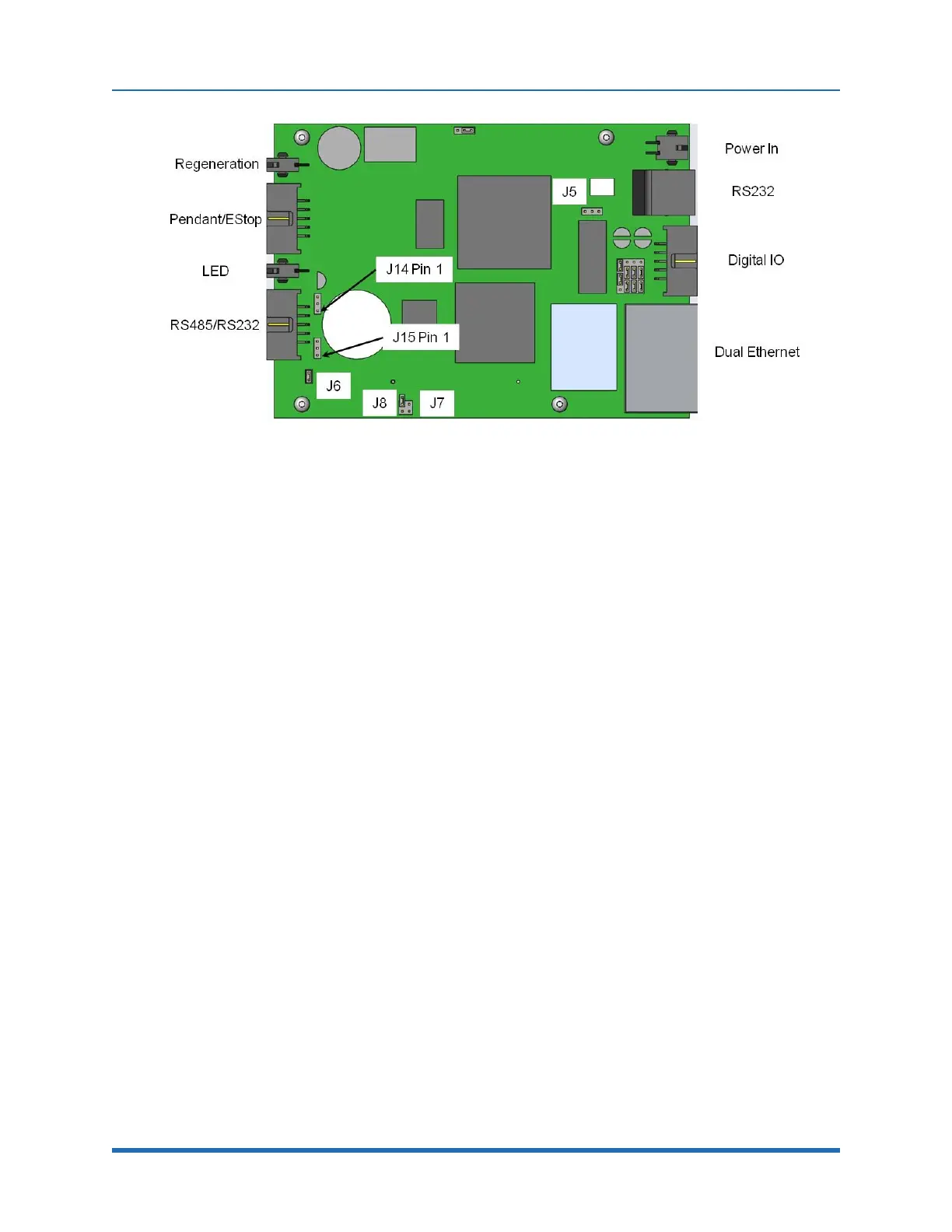
Figure 6-1: Board, J6
There is a configuration parameter in the PAC files which determines whether the Linear Axis is
configured to add to the robot’s Y Cartesian Axis or X Cartesian Axis. The 5
th
element of the
"Kinematic dimension constants" (16050) will specify the orientation of the rail. A value of 0 has the
rail moving along +Y. To have the rail move along +X, the 5
th
parameter must be set to -90
(degrees).
The Linear Axis Option is configured so that the zero position is in the middle of the range of travel.
The software is configured so that the Linear Axis position is added to either the Y-axis or X-axis
Cartesian position of the gripper. The Linear Axis appears as Joint 6 in Joint Coordinates and in the
Virtual Pendant Coordinates. It may be moved by the “Move.OneAxis” command by selecting Joint
6.
The factory test program which is shipped with each robot includes sample code to move the Linear
Axis.
Controlling the PreciseFlex Servo Grippers
Overview
The 23 Newton PreciseFlex Servo Gripper with spring return contains a brushless servo motor with
an incremental encoder with both counting and motor phase tracks. At power up the encoder
provides motor commutation information for a brief period, and then switches the incremental
encoder A, B, and Z signals onto the same set of wires. This allows the motor commutation to be
initialized at start-up without any motion.
The motor has a 12 tooth pinion gear cut directly on the motor shaft. This pinion drives a pair of
opposing racks to open and close a set of finger mounts which are attached to linear ball slides.
Various fingers can be attached to the finger mounts.
83
Copyright © 2023, Brooks Automation