Brooks Automation 7. Service Procedures
Part Number: PF40-DI-00010 Rev. A Replacing the Main Harness
Step Action
4.
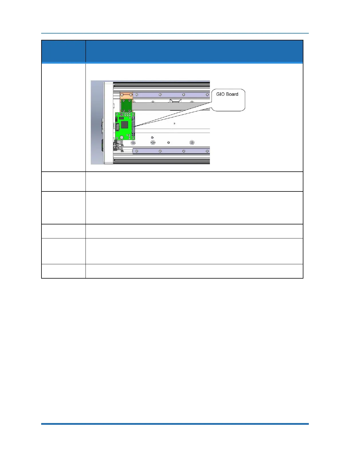
Install the GIO Board in the linear axis using the (4) M3 X 10 mm SHCS and lockwashers.
5.
Remove the termination resistor from the 10-pin connector plug attached by (4) wires to the 9-
pin Dsub Pendant connector and plug the 10-pin connector into the GIO board.
6.
Install the GIO output pigtail by plugging the 26-pin connector into to the GIO board and
attaching the 25-pin Dsub connector to the end cap with the 4-40 standoffs provided. Make an
accordion fold with the extra ribbon cable and tie wrap to hold the fold down over the GIO
board.
7.
Replace the covers.
8.
Set value 8 in Data ID 151 to “GIO_8”, so that this ID reads “<Controller Serial No>”, “GSB_1”,
“”,“”,“”,”“”,“”,GIO_8”
This parameter may be found in Setup/Parameter Database/Controller/System ID.
9.
GIO signals may then be checked under Control Panels/Remote IO/Servo Node 8.
Replacing the Main Harness
Replacement of the Main Robot Harness is typically only performed at the factory. The Main Robot
Harness is intended to last for the life of the robot.
Replacing the Outer Link Harness
The Outer Link Harness is composed of three cables: Harness, FFC, J4 Motor, (PF0H-MA-00002-
02-E3), Harness, FFC, J4 Encoder (PF0H-MA-00005-02-E3), and Harness, Gripper Controller
(PF0H-MA-00014).
Copyright © 2023, Brooks Automation
130