5. Hardware Reference (Undefined variable: MyVariables.ProductName)
System Schematics Part Number: PF40-DI-00010 Rev. A
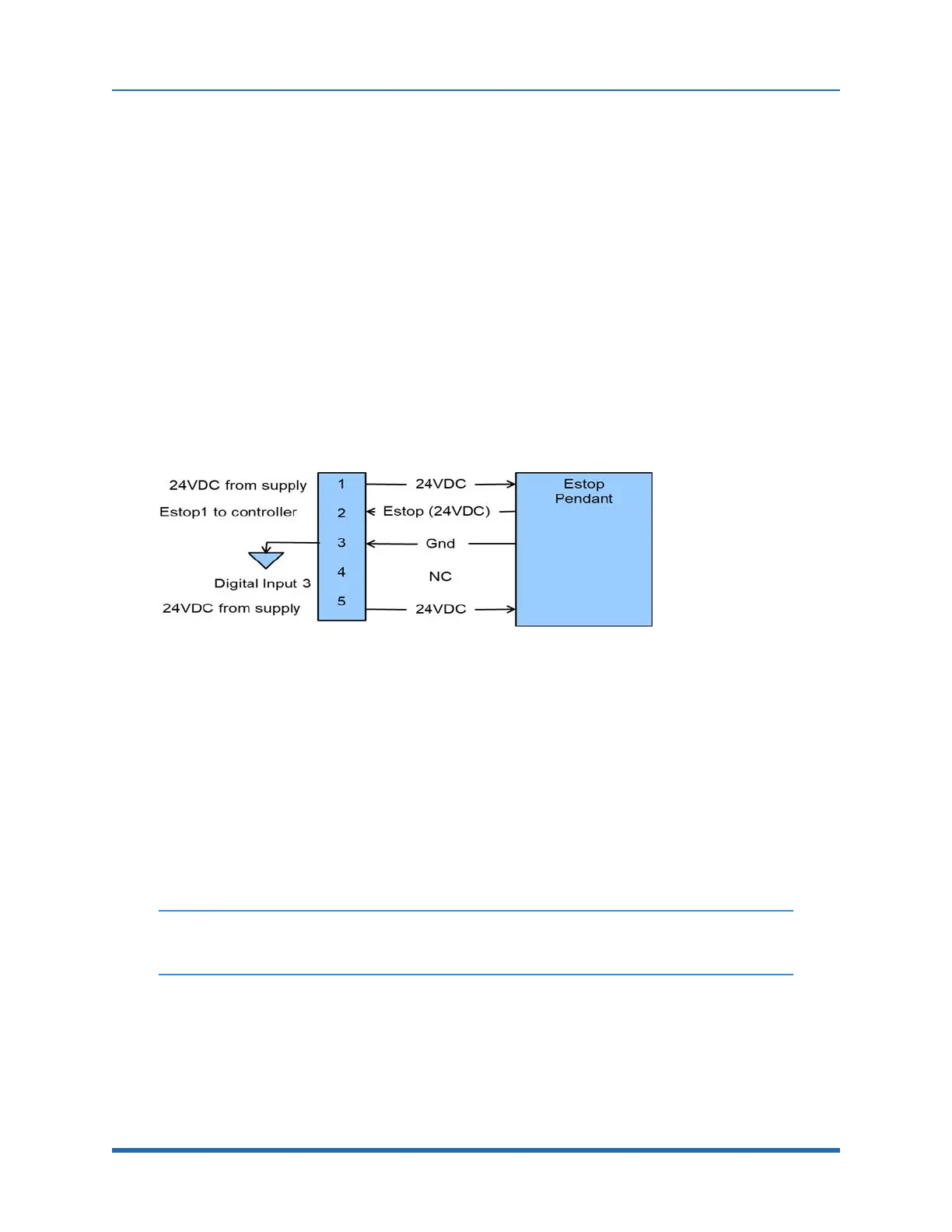
E-Stop Connector
The standard E-Stop connector is the green Phoenix connector on the Facilities Panel. Note the E-
Stop pins on the MCP Interface (Figure 5-21) are in series with the E-Stop signals on the Phoenix E-
Stop connector.
An E-Stop box or circuit can be plugged into either one of these two connectors. However in order
for the robot to allow motor power to be enabled the E-Stop circuit must connect 24 VDC to E-Stop1
in both of these two connectors. If no E-Stop box or circuit is connected, then the circuit must be
completed with a jumper from pin 1 to pin 2 on the Phoenix connector or from pin 1 to pin 6 on the
MCP connector. The robot is shipped with a Phoenix jumper plug (PN 1851070) and a jumper plug
in the 9-pin Dsub connector that satisfy these requirements. Unlike the Digital IO circuits, the E-Stop
circuit cannot be configured as "Sourcing" or "Sinking." If a remote signal (for example from a PLC)
is used to trigger E-Stop, it should be wired to a relay that closes the circuit between pins 1 and 2.
When the robot is mounted on a Linear Axis, the MCP Interface is extended to the end cap of the
Linear Axis.
Figure 5-21: E-Stop Pins on the MCP Interface
MCP / E-Stop Interface
The MCP interface includes the signals necessary to connect a Manual Control Pendant, secondary
E-Stop circuit, or an external RS-485 Remote IO Module. These signals are provided in a DB9
female connector mounted on the robot’s Facilities Panel and on the end cap of the optional Linear
Axis.
NOTE: The E-Stop pins on the MCP Interface are in series with the E-Stop signals on
the Phoenix E-Stop connector.
An E-Stop box or circuit can be plugged into either one of these two connectors. However, in order
for the robot to allow motor power to be enabled, the E-Stop circuit must connect 24 VDC to E-Stop1
in one of these two connectors. If no E-Stop box or circuit is connected, both circuits must be
completed with jumper plugs. (The robot is shipped with a Phoenix jumper plug (PN 1851070) and a
Dsub jumper plug that satisfy these requirements.)
67
Copyright © 2023, Brooks Automation