7. Service Procedures (Undefined variable: MyVariables.ProductName)
Tensioning the J2 Belt Part Number: PF40-DI-00010 Rev. A
Step Action
3.
Remove the Front Cover by lifting it out vertically.
4.
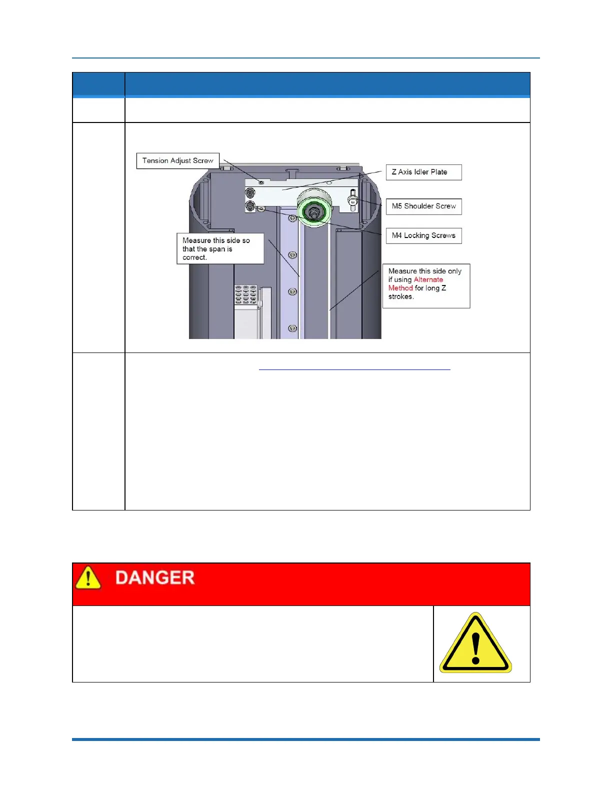
Loosen the (2) M4 locking screws and the M5 shoulder screw on the Z idler plate.
5.
The tension is set to the value in Appendix E: Belt Tensions, Gates Tension Meter by adjusting the
M5 set screw which pushes on a spring in the Z Axis Idler Plate. Re-tighten the 3 screws and
replace the Front Cover and Top Plate.
Alternate Method:
For the 750 mm and 1160 mm Z travel robots, it can sometimes be difficult to get a good tension
reading for the spans for these long belts, which are 880 mm and 1290 mm respectively and as a
result have low vibration frequencies. In this case it may be easier to position the Z carriage so that
the span from the top idler pulley to the Z carriage is 530 mm, which is the span for the 400 mm Z
stroke when measured on the left hand side of the belt as shown above. With the carriage at this
location with a span of 530 mm, for these longer travel Z strokes, a user can then measure the
tension on the right hand side of the belt, and use the values for tension and frequency for the 400
mm Z stroke.
Tensioning the J2 Belt
Electrical Shock
Before tensioning the timing belts, the AC power should be disconnected. Removing the
front cover allows access to the AC power terminals.
103
Copyright © 2023, Brooks Automation