3. Collaborative Robot Safety (Undefined variable: MyVariables.ProductName)
Robot Workcell Design Part Number: PF40-DI-00010 Rev. A
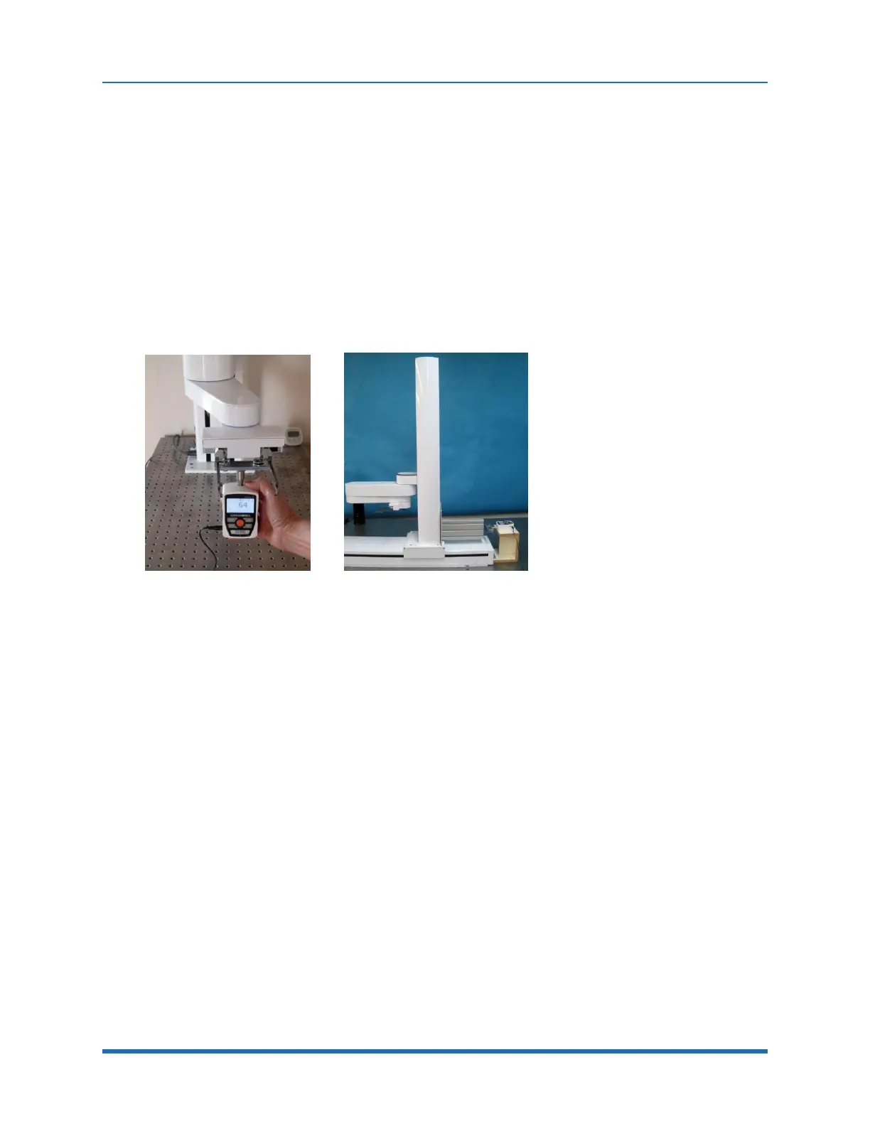
compression constant of a human hand (from figure 2) is attached to the force gauge. For the Z test
the robot is driven downwards in the Z direction at various speeds and crashes into the hand
simulator attached to the force gauge. For the Horizontal tests the robot is driven horizontally at
various speeds into the hand simulator. A worse case horizontal crash is measured with arm at full
extension and J2 (the shoulder) rotating the arm at various speeds into the force gauge. This data is
shown under the “J2 rot” column.
A typical case of a robot contacting a person is bumping into the person in free space where the
person is not trapped against a hard surface or where there is some distance between the person’s
appendage and the hard surface. For the PF400, any distance over 20 mm is adequate for the
person to stop the robot with a force less than 40 N in the horizontal plane and approximately 60 N
in the –Z direction. Figure 3-4 shows the setup for the free-space collision test.
Figure 3-4: Free Space Collision Test and Linear Rail Test
Robot Workcell Design
Introduction. The PF400 is always configured as a “Collaborative Robot.” It is designed for
light duty applications with a payload 500 gms. The plate handler robot is designed so that
maximum forces in the horizontal plane do not exceed approximately 60 Newtons and maximum
slow motion forces in the downward Z direction do not exceed 60 Newtons. At the maximum Z
downwards speed of 500 mm/sec, crash forces can reach 206 N for collision with a hard surface.
High speed impacts for the robot or linear rail, which could trap an operator against a surface may
be avoided by teaching an “Approach” position which is a greater distance from a fixture than any
operator appendage that might enter the workcell, and first moving to this “Approach” position at
high speed, then moving to the final position at a slow speed which will not create excessive force in
the event of a trapped operator.
Work cell Design Recommendations for the PF400
Work cell designers are referred to EN ISO 10218-2:2011 for information on designing safe work
cells.
35
Copyright © 2023, Brooks Automation