EasyManuals Logo

Brooks PreciseFlex 400 User Manual

Brooks PreciseFlex 400
187 pages
To Next Page IconTo Next Page
To Previous Page IconTo Previous Page
Page #53 background imageLoading...
Page #53 background image
Brooks Automation 4. Installation Information
Part Number: PF40-DI-00010 Rev. A Linear Axis Mounting Dimensions
Linear Axis Mounting Dimensions
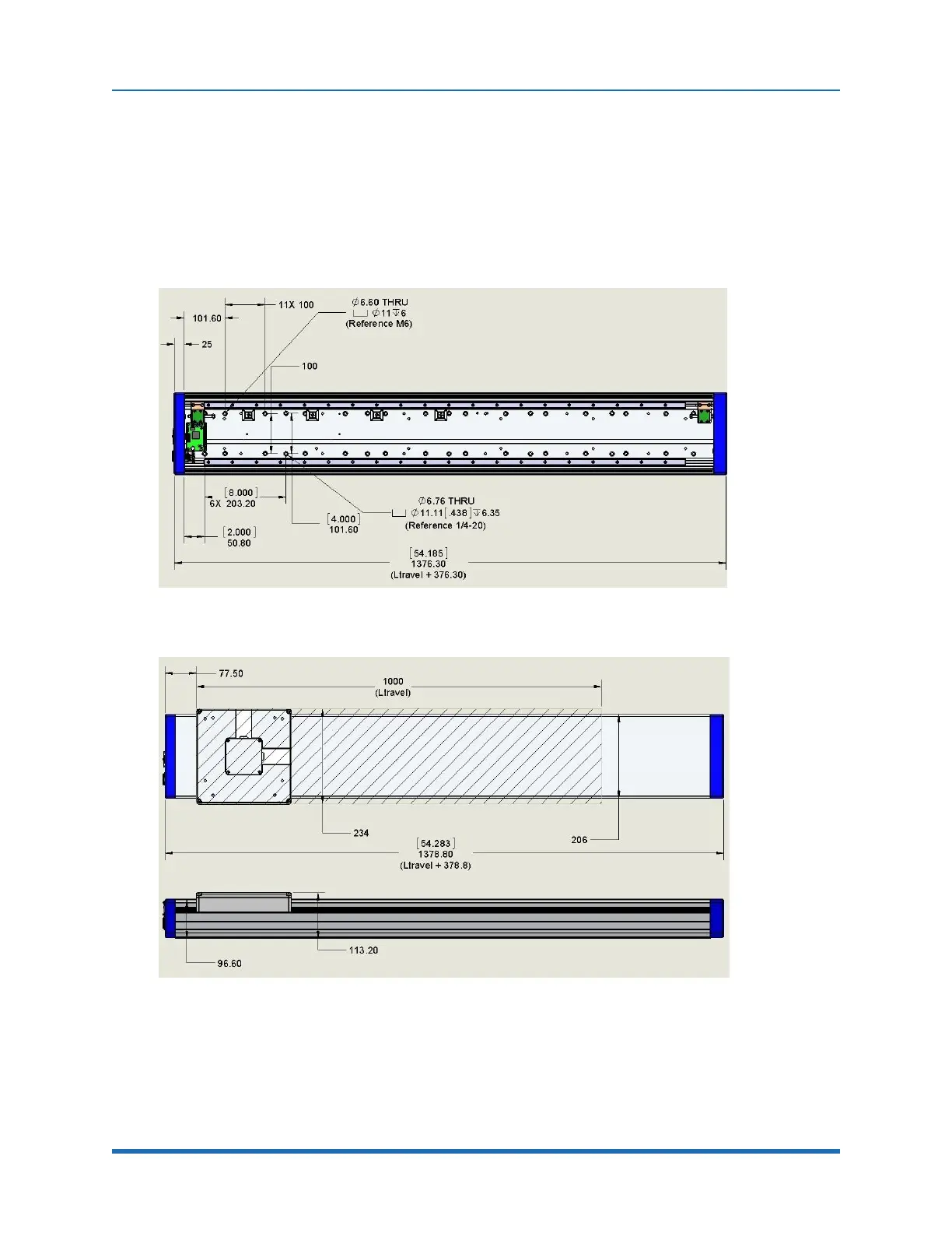
The linear axis (Figure 4-8 and Figure 4-9 show the dimensions) has both an M6 and ¼-20 hole
pattern inside the extrusion. Loosen the connector end cap slightly and remove the top cover to
access these holes patterns. When replacing the top cover, be sure the tape seals are inside the
slot in the top cover and not crushed.
Figure 4-8: Linear Axis Mounting Dimensions
Figure 4-9: Linear Axis Mounting Dimensions
Copyright © 2023, Brooks Automation
44

Table of Contents

Questions and Answers:

Question and Answer IconNeed help?

Do you have a question about the Brooks PreciseFlex 400 and is the answer not in the manual?

Brooks PreciseFlex 400 Specifications

General IconGeneral
BrandBrooks
ModelPreciseFlex 400
CategoryRobotics
LanguageEnglish

Related product manuals