Brooks Automation 5. Hardware Reference
Part Number: PF40-DI-00010 Rev. A System Schematics
If a Manual Control Pendant is not connected to the secondary RS-232 port provided in this
connector, this serial interface can be accessed via a GPL procedure as device "/dev/com2" for
general communications purposes.
NOTE: Unlike the primary serial interface, this secondary serial interface does not
support flow control.The RS-485 port is used internally to communicate with the
gripper controller and is also be used for the Remote IO option. As such it has a
dedicated protocol and is not available for general use. See Table 5-2 for more
information.
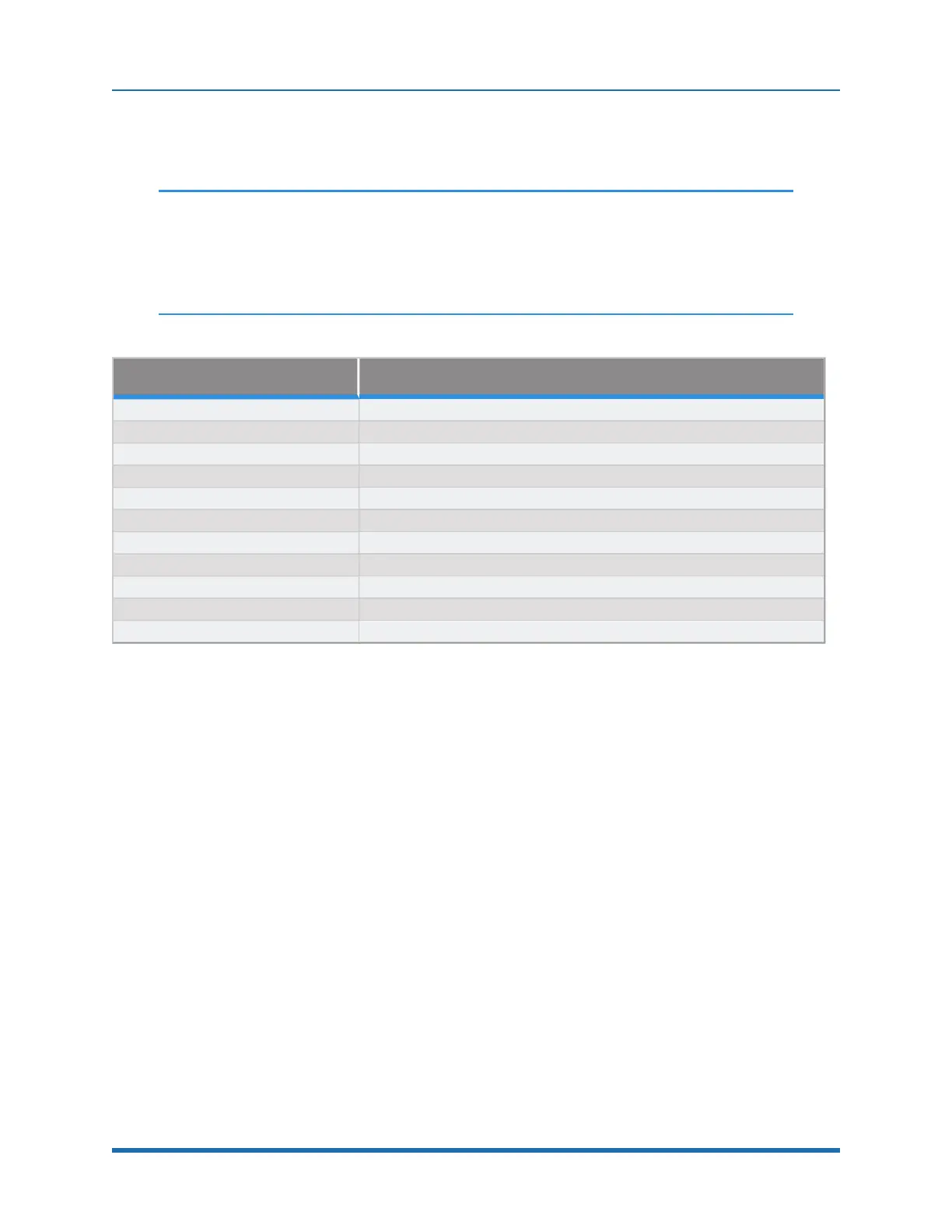
Pin Description
1 24 VDC
2 RS-232 TXD
3 RS-232 RXD
4 RS-485-
5 Gnd
6 E-Stop1
7 E-Stop Daisy Chain
8 48 VDC
9 RS-485+
Interface Panel Connector Part No DB9 Female Connector AMP 5747150-7
User Plug Part No DB9 Male Plug Amp 1658655-1 (crimp) Pins 22-26AWG 745254-6
Table 5-2: Pins, Connector, and Plug
Digital Input and Output Signals
Digital Input Signals
The standard PreciseFlex
TM
400 robot provides one general-purpose optically isolated digital input
signal at the Facilities Panel (in addition to those signals that are available at the Gripper Control
Board). This line is accessed in the Phoenix 5-pin E-Stop connector and is connected to Digital
Input 3 in the controller. See Figure 5-22.
Copyright © 2023, Brooks Automation
68