Brooks Automation 3. Collaborative Robot Safety
Part Number: PF40-DI-00010 Rev. A Test Procedure for the PF400
can be demonstrated by dropping the CPU into debug mode via the serial debug port which simulates
a software crash. This will disable motor power. TUV has verified this fail-safe operation.
8. Position error, force limits and collision detection. The PF400 has a control function that limits
the maximum force of any axis. This function is used to limit the Z crushing force in the 500 gm robot.
If the force limit is exceeded due to a collision, a position tracking error will be generated and will
generate either a Category 2 or Category 1 E-Stop, depending on the magnitude of the error. The
controller continuously monitors the commanded robot trajectory versus the actual position at a rate
of 2000 Hz. If the position error exceeds a threshold, typically set to a few tenths of a degree, the
controller stops the robot motion. This function works at all times if the controller CPU is operating.
This can be demonstrated by pushing on the robot while stationary to generate a position envelope
error. There are redundant monitor functions that check that the position error and force limits are
operating correctly. This is a CAT 3 compliant function. TUV has verified this fail-safe operation.
9. Motor overheating. PreciseFlex controllers have a “motor duty cycle” monitor that computes the
average power level in a motor and shuts down the motor power if a maximum permissible power
level is exceeded. This can be demonstrated by driving an axis back and forth rapidly enough that the
maximum duty cycle is exceeded and the motor power is turned off.
Test Procedure for the PF400
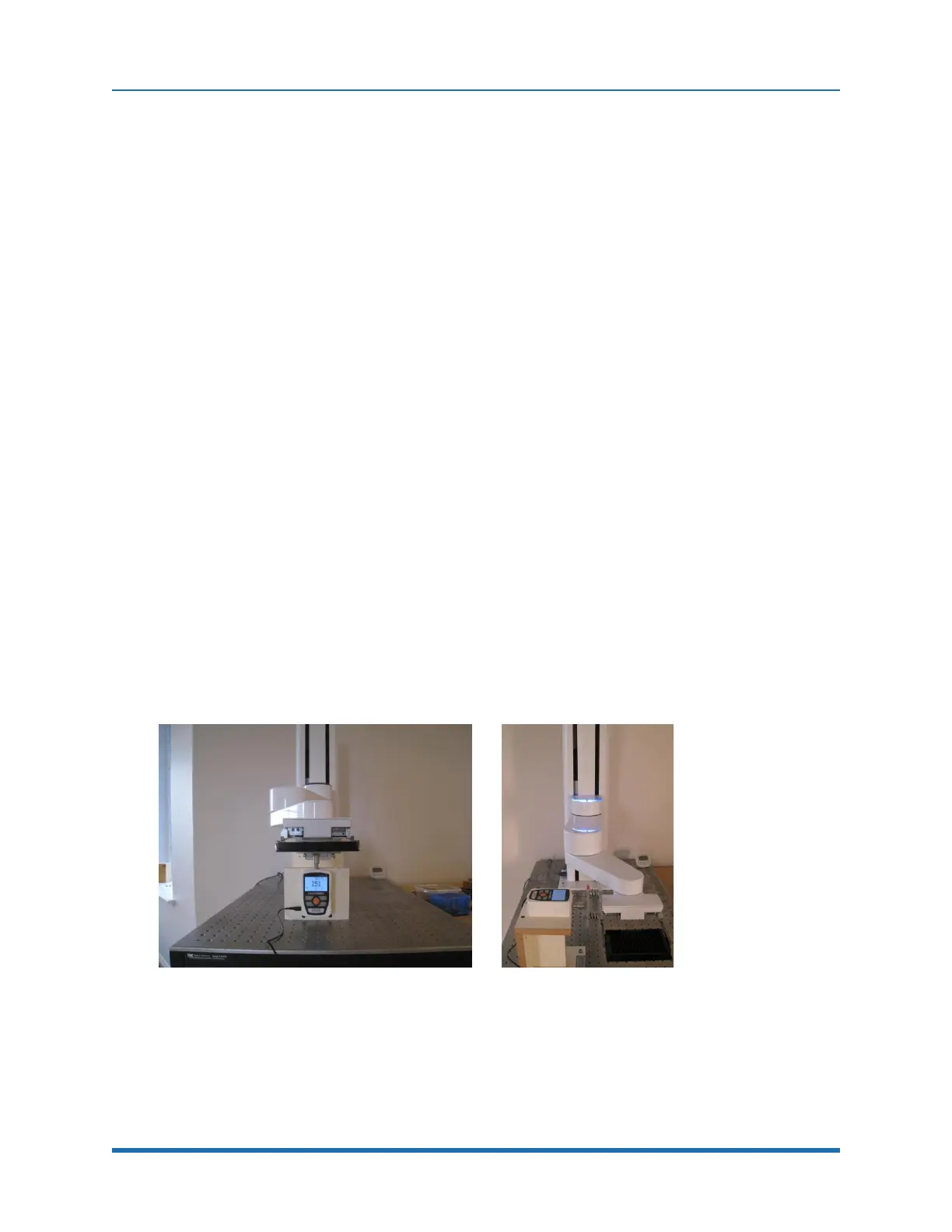
The worst-case crash condition for the PF400 is when the Z-axis is moving downwards at the 100%
speed of 500 mm/sec and crashes into the relatively non-compliant hand of an operator pinching
the hand into a hard surface. Figure 3-3 shows the test setup to measure this force.
Figure 3-3: Vertical and Horizontal Test Setup
In this test setup a digital force gauge (traceable to NIST standards) is mounted below (or to the left
for horizontal testing) of the gripper of the robot and a “hand compliance simulator” consisting of two
plates separated by compression springs with a compression constant of 75 N/mm equal to the
Copyright © 2023, Brooks Automation
34