5. Hardware Reference (Undefined variable: MyVariables.ProductName)
System Schematics Part Number: PF40-DI-00010 Rev. A
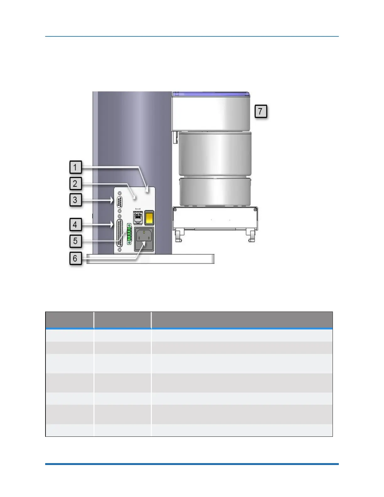
Facilities Panel
The Facilities Panel (Figure 5-20 and Table 5-1) is located at the base of the robot.
Figure 5-20: Facilities Panel
Annotation Name Description
1 Power Switch Lighted Power Switch
2 Ethernet Connector For Ethernet to Computer Cable
3
9 Pin2D Sub
Connector
Contains RS-232 Serial Port, 24 VDC, Gnd can be used for optional
teach pendant
4
25 Pin D Sub
Connector
For optional DIO module, 12 inputs, 8 outputs
5 E-Stop Connector E-Stop and Cell Interlock Signals
6 Power Entry Module
For IEC plug.
Contains dual fuse drawer.
7 Power Status Light Blinks to indicate the power status.
Table 5-1: Facilities Panel key
65
Copyright © 2023, Brooks Automation