6-71 Confidential
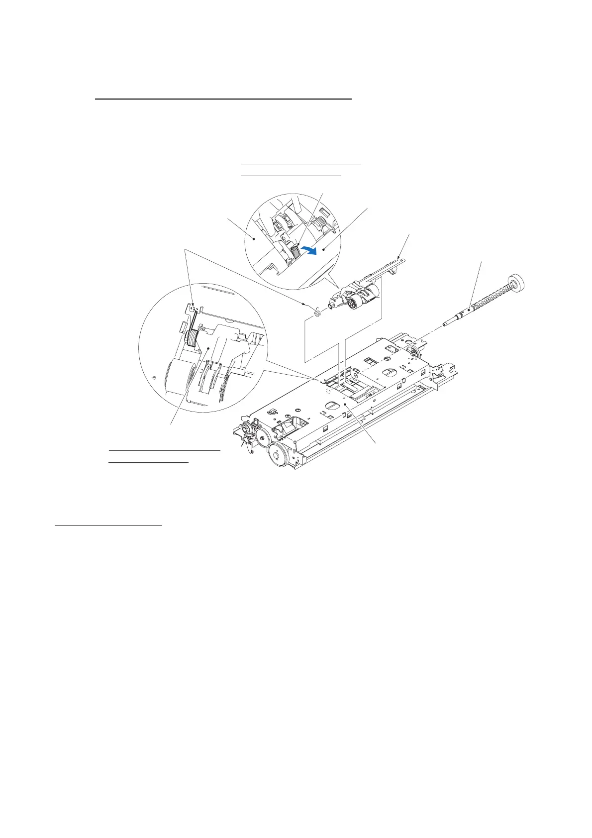
Paper pull-in gear shaft and paper pull-in roller holder
(14) Press the lock arm and pull out the paper pull-in gear shaft to the right.
(15) Lift the paper pull-in roller holder up and out of the engine unit, together with its spring.
(6_62)
Lock arm
Paper pull-in roller holder
Paper pull-in roller spring
Paper pull-in roller holder
Fitting the paper pull-in roller
spring into the cutout
Engine unit placed upside down
Paper pull-in gear shaft
Pressing the lock arm to remove
the paper pull-in gear shaft
Paper pull-in roller holder
Engine unit
Assembling Notes
• When setting the paper pull-in roller holder back into place, fit the longer end of the paper pull-in
roller spring into the cutout provided in the engine chassis.
While holding down the paper pull-in roller holder lightly, insert the paper pull-in gear shaft
from the right until it locks.
• When mounting the paper feed motor, route its harness as shown on the previous page and secure
the motor with two screws with the label facing towards the front.
• When attaching the PF encoder disk to the PF roller gear L, using a spatular tool makes the job
easier. Put on clean gloves to protect the disk surface from dust or fingerprints.
• Before mounting the inner chute on the engine unit, set the registration sensor actuator and its
spring. Also set the registration sensor PCB and route the PF encoder/registration sensor harness
and the paper feed motor harness. See page 6-69.
• When mounting the carriage motor, face the label outwards (see page 6-68).
 Loading...