Assembly
3
CLS Pro 600 – Line and Contrast Sensor 29/108
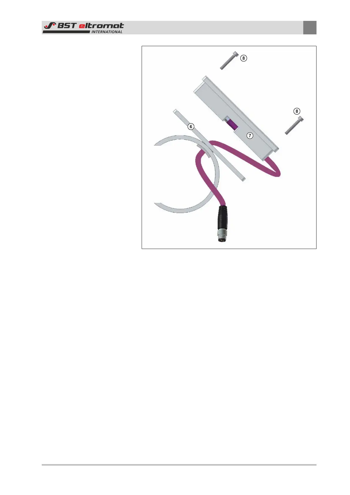
Fig.25: Unscrew the securing screws
⑥
Mounting Plate
⑦
Control Panel
⑧
Fastening Screws
4. Unscrew the four control panel securing screws ⑧ and put
them aside. These screws will be needed for the wall mounting
later on.
5. Pull the control panel ⑦ out of the mounting plate ⑥. Now
pull the connecting cable and the plug carefully through the
cut-out in the mounting plate.