3
Assembly
30/108 CLS Pro 600 – Line and Contrast Sensor
Assembly:
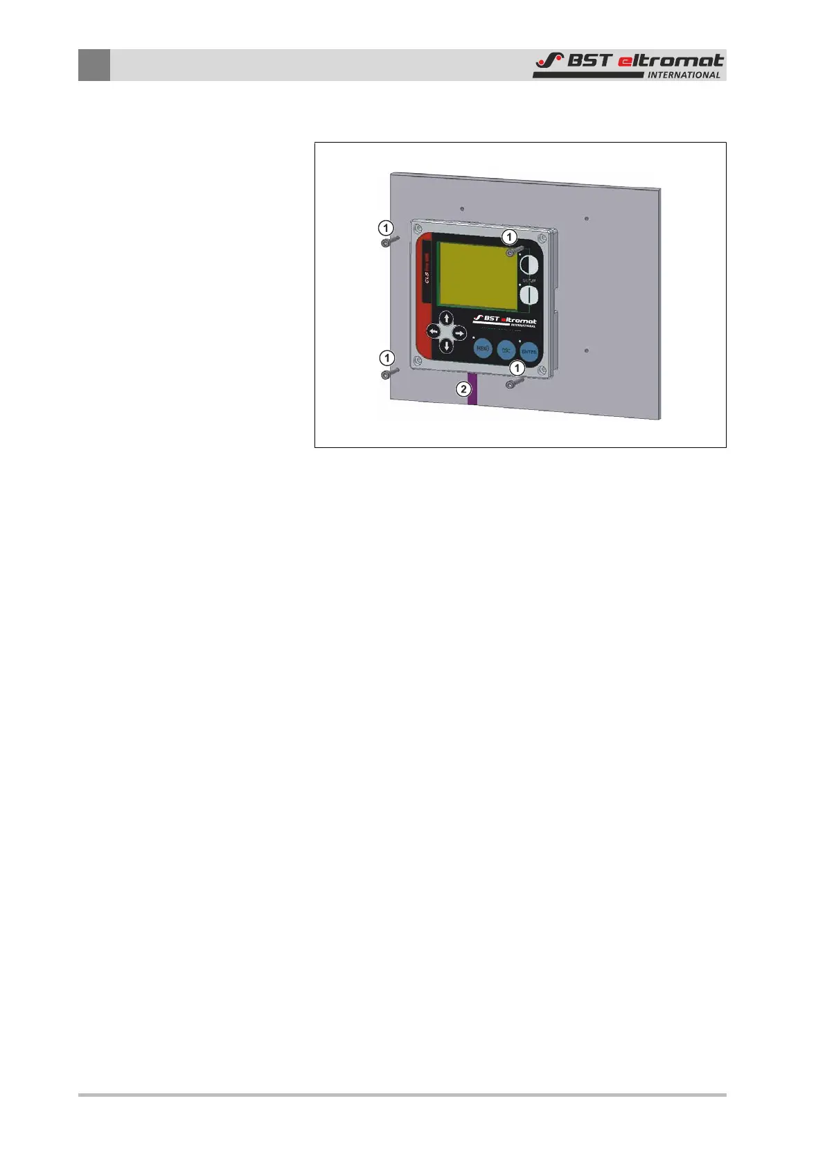
Fig.26: Mount the control panel
①
Fastening Screws
②
Cable (do not crush or clamp)
1. Fit the M3 threads in the holes as shown in the securing screw
hole template.
2. Use the four M3 screws to screw the control panel on. The four
hexagon screws that secured the control panel to the sensor
when the unit was delivered can be used for this.
3. Use the optional extension cable to connect the control panel
to the sensor.
4. Plug the extension cable connector into the sensor’s X100
socket.