3
Assembly
32/108 CLS Pro 600 – Line and Contrast Sensor
1. Unplug the control panel connecting cable from the sensor
(plug X100).
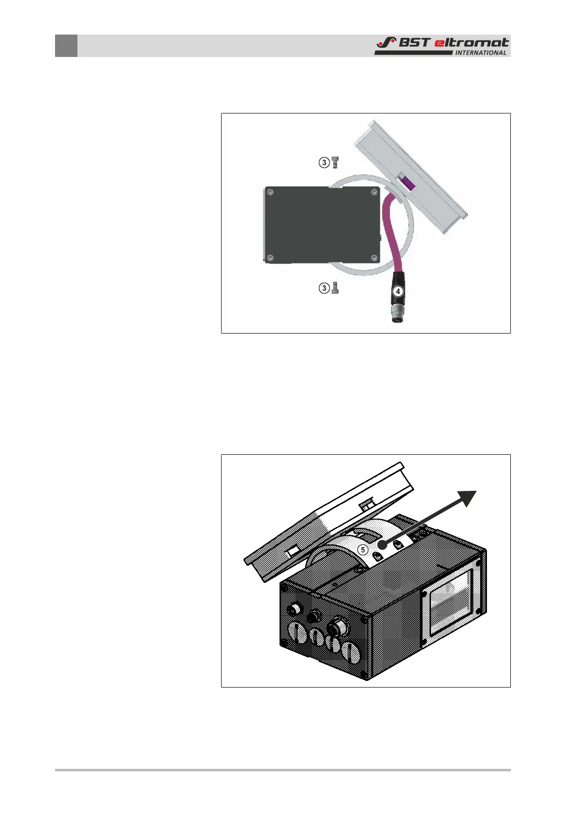
Fig.29: Unscrew the securing screws
③
Fastening Screws
④
Plug
2. Unscrew the four control panel securing screws and put them
aside. These screws will be needed for the console mounting
later on.
Fig.30: Take off the control panel