Assembly
3
CLS Pro 600 – Line and Contrast Sensor 33/108
⑤
Holding ring with mounted control panel
3. Pull the control panel out of the mounting plate. Pull the con-
necting cable and the plug carefully through the hole in the
mounting plate.
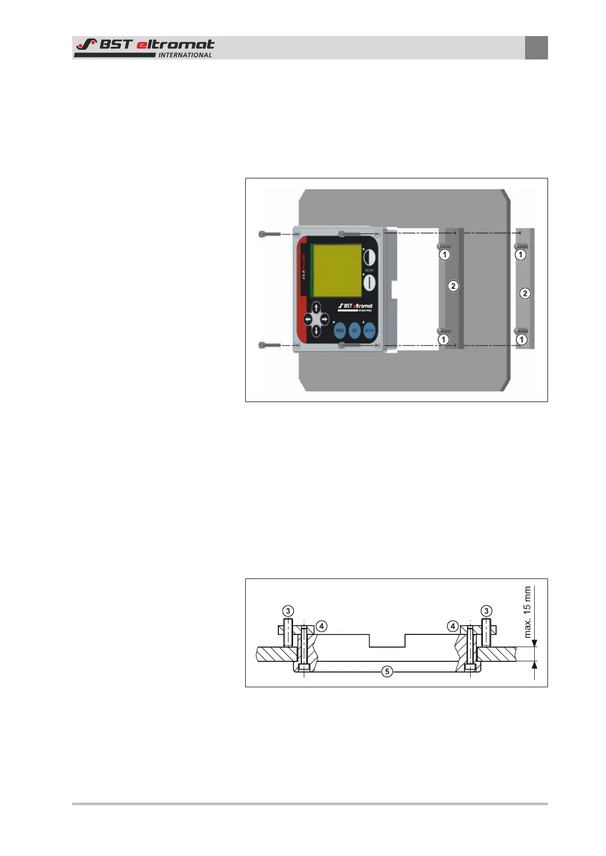
Assembly:
Fig.31: Installing the control panel
①
Threaded Pins
②
Securing Plates
1. Cut out the section.
2. Carefully push the control panel into the cut-out section.
3. Use two of the securing screws to screw the two securing
plates (part of the installation kit) onto the back of the control
panel. The four hexagon screws that secured the control panel
to the sensor when the unit was delivered can be used for this.
Fig.32: Top View
③
Threaded Pin
④
Securing Plate
⑤
Control Panel