2007 Buell P3: Chassis 2-61
HOME
FOOTPEGS AND FOOTPEG SUPPORT BRACKETS 2.21
REMOVAL
Footpeg
1. See Figure 2-102. Remove cotter pin (3).
2. Remove clevis pin (4).
3. Remove spacer (7, rear peg only).
4. Remove footpeg.
Footpeg Support Bracket
1. Remove seat. See 2.28 SEAT.
2. See Figure 2-103. On left side remove oil tank drain
hose, breather drain hose, clamp and fastener.
3. On right side remove rear master cylinder, spacers, res-
ervoir, and brake pedal.
4. See Figure 2-102. Remove mounting bolts located
behind footpeg support bracket.
5. Remove footpeg support bracket.
INSTALLATION
Footpeg Support Bracket
1. Align footpeg support mounting bracket and spacer with
mounting holes on frame.
2. Install mounting bolts and washers. Tighten fasteners to
25-30 ft-lbs. (34-41 Nm).
3. See Figure 2-103. On left side install clamp with oil tank
drain hose and breather hose.
4. On right side install rear master cylinder, spacers, reser-
voir, and brake pedal. See 2.13 REAR BRAKE MASTER
CYLINDER.
11WARNING1WARNING
After installing seat, pull upward on front of seat to be
sure it is in locked position. While riding, a loose seat can
shift causing loss of control, which could result in death
or serious injury. (00070a)
5. Install seat. See 2.28 SEAT.
Footpeg
1. See Figure 2-102. Align footpeg mounting holes with
footpeg support bracket mounting holes.
2. Insert dowel pin (and on rear peg, spacer) through
mounting holes.
3. Install new cotter pin.
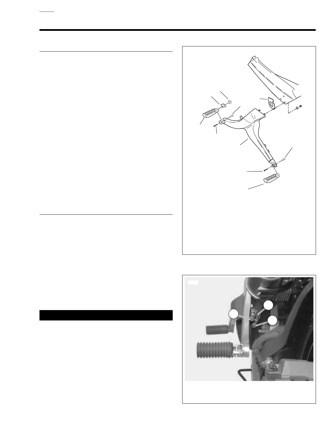
Figure 2-102. Footpeg Support Bracket (Left Side)
Figure 2-103. Left Side Footpeg Support Bracket
a0130x2x
1. Footrest support bracket
2. Front footpeg
3. Cotter pin
4. Clevis pin
5. Rear footpeg
6. Index plate
7. Spacer
8. Spacer
3
4
2
5
8
4
7
6
1
3
1. Clamp
2. Oil tank drain hose
3. Breather hose
7742
1
2
3