2007 Buell P3: Electrical 7-13
HOME
BANK ANGLE SENSOR 7.5
REMOVAL
1. Remove seat. See 2.28 SEAT.
11WARNING1WARNING
To prevent accidental vehicle start-up, which could
cause death or serious injury, disconnect negative (-)
battery cable before proceeding. (00048a)
2. Disconnect negative battery cable from battery.
11WARNING1WARNING
Disconnect negative (-) battery cable first. If positive (+)
cable should contact ground with negative (-) cable con-
nected, the resulting sparks can cause a battery explo-
sion, which could result in death or serious injury.
(00049a)
3. See Figure 7-12. Remove circuit breaker from mounting
bracket.
4. Remove allen head screw from mounting bracket while
holding locknut on bank angle sensor side.
5. Remove bank angle sensor from its mounting location.
6. Disconnect connector [134] from bank angle sensor.
7. Remove bank angle sensor.
INSTALLATION
1. Connect connector [134] to new bank angle sensor.
2. See Figure 7-12. Position bank angle sensor in mounting
position on circuit breaker bracket mounting screw. Make
sure sensor locating post engages hole in trunk to
ensure proper alignment of sensor.
3. Install bank angle sensor with allen screw and locknut.
Tighten screw to 25-27 in-lbs (2.8-3.1 Nm).
4. Install circuit breaker to circuit breaker mounting bracket.
Connect positive (+) battery cable first. If positive (+)
cable should contact ground with negative (-) cable con-
nected, the resulting sparks can cause a battery explo-
sion, which could result in death or serious injury.
(00068a)
5. Install negative battery cable to battery terminal. Tighten
fastener to 72-96 in-lbs (8-11 Nm).
After installing seat, pull upward on front of seat to be
sure it is in locked position. While riding, a loose seat can
shift causing loss of control, which could result in death
or serious injury. (00070a)
6. Install seat. See 2.28 SEAT.
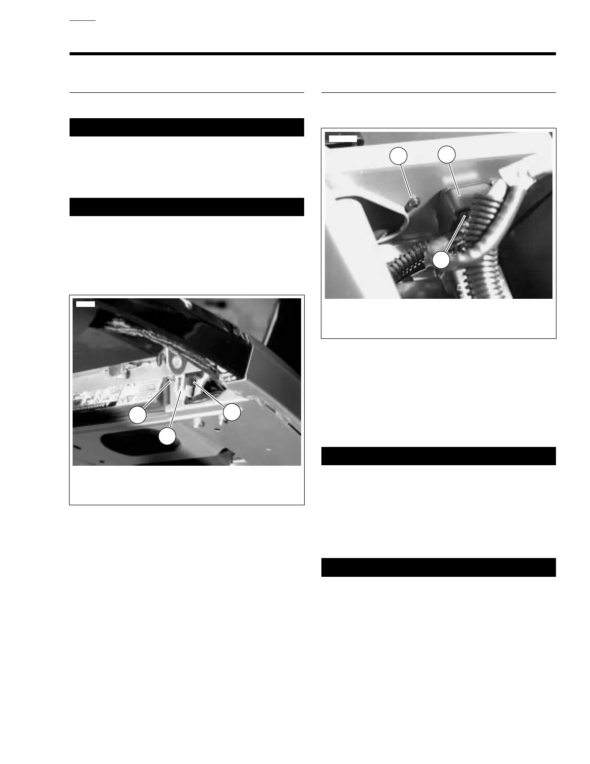
Figure 7-11. Bank Angle Sensor Removal
8261
1. Bank angle sensor
2. Connector [134]
3. Locknut
1
2
3
Figure 7-12. Bank Angle Sensor Installation
8262
1. Circuit breaker bracket
2. Allen screw
3. Locating post
2
1
3