5-10 2007 Buell P3: Electric Starter
HOME
STARTER SYSTEM TESTING 5.6
“ON-MOTORCYCLE” TESTS
Starter Relay Test
1. See Figure 5-6. Locate starter relay. The relay is
attached to relay connector [123] located to the right of
the battery underneath the seat.
2. To test relay, proceed to Step 3. If installing a
new
starter
relay, remove old relay. Install relay connector [123] to
new
relay.
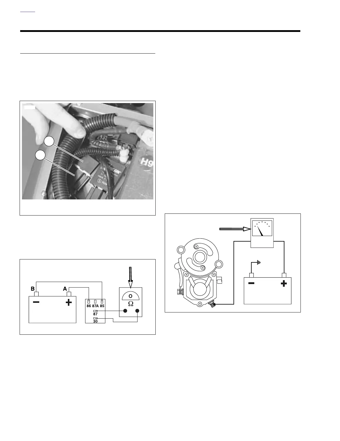
3. See Figure 5-7. Obtain a 12 volt battery and a continuity
tester or ohmmeter.
a. Pull relay from relay block.
b. Connect positive battery lead to the 86 terminal.
c. Connect negative battery lead to the 85 terminal to
energize relay.
d. Check for continuity between the 30 and 87 termi-
nals. A good relay shows continuity (continuity tester
lamp “on” or a zero ohm reading on the ohmmeter).
A malfunctioning relay will not show continuity and
must be replaced.
4. If starter relay is functioning properly, proceed to
STARTER CURRENT DRAW TEST.
Starter Current Draw Test
NOTES
●
Engine temperature should be stable and at room tem-
perature.
●
Battery should be fully charged.
See Figure 5-8. Check starter current draw with an induction
ammeter before disconnecting battery. Proceed as follows:
1. Verify that transmission is in neutral. Disconnect spark
plug wires from spark plug terminals.
2. Clamp induction ammeter over positive battery cable
next to starter.
3. With ignition key switch ON, turn engine over by pressing
starter switch while taking a reading on the ammeter.
Disregard initial high current reading which is normal
when engine is first turned over.
a. Typical starter current draw will range between 80-
130 amperes.
b. If starter current draw exceeds 130 amperes, then
the problem may be in the starter or starter drive.
Remove starter for further tests. See 5.7 STARTER.
Figure 5-6. Starter Relay Connector
Figure 5-7. Starter Relay Test with Ohmmeter
7765
1. Starter relay
2. Connector [123]
2
1
a0166x5x
Figure 5-8. Starter Draw Test with Induction Ammeter
a0167x5x