2007 Buell P3: Electrical 7-57
HOME
HORN 7.22
REMOVAL
1. Pull bottom of horn forward slightly and remove nut (met-
ric) from back of horn.
2. See Figure 7-75. Detach Y/BK power wire and BK
ground wire from terminal clips.
3. Remove horn from motorcycle.
INSTALLATION
1. See Figure 7-75. Connect Y/BK power wire and BK
ground wire to terminal clips.
2. Attach horn to bracket with nut (metric). Tighten nut to
25-33 in-lbs (2.6-3.7 Nm).
3. Check horn operation. If horn does not sound or fails to
function satisfactorily, see TROUBLESHOOTING.
a. Turn ignition key switch to IGN.
b. Press horn switch to activate horn.
c. Turn ignition key switch to OFF.
TROUBLESHOOTING
1. If the horn does not sound or fails to function satisfacto-
rily, check for the following conditions:
a. Discharged battery.
b. Loose, frayed or damaged wiring leading to horn ter-
minal.
2. If battery has a satisfactory charge and wiring appears to
be in good condition, test horn grounds and switch using
voltmeter.
a. See Figure 7-75. Remove Y/BK power and BK
ground wires from terminal clips.
b. Connect voltmeter positive (+) lead to Y/BK wire.
c. Connect voltmeter negative (–) lead to ground.
d. Turn ignition key switch to IGN.
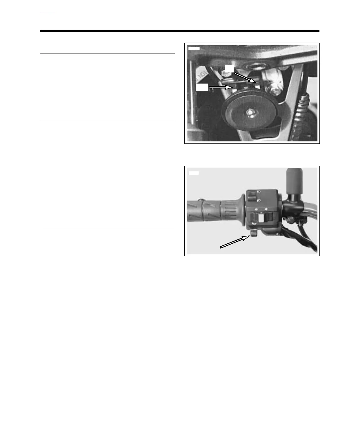
3. See Figure 7-76. Depress horn switch and observe volt-
meter reading.
a. If battery voltage is present, horn or horn grounding
is faulty. If horn is faulty, replace unit as an assembly.
The horn is not repairable.
b. If battery voltage is not present, either horn switch or
wiring to horn is faulty. If horn switch is faulty,
replace left handlebar switch. See 7.21 HANDLE-
BAR SWITCHES.
Figure 7-75. Horn Assembly
Figure 7-76. Horn Switch Location