6-18 2007 Buell P3: Drive/Transmission
HOME
TRANSMISSION CASE 6.6
GENERAL
The rear compartment of the left and right crankcase halves
form the transmission case. Servicing of transmission compo-
nents requires removing the engine and disassembling (split-
ting) the crankcase.
REMOVAL
1. Remove transmission sprocket. See 6.14 TRANSMIS-
SION SPROCKET.
2. Remove engine from chassis. See 3.3 STRIPPING
MOTORCYCLE FOR ENGINE SERVICE.
3. Support engine using ENGINE SUPPORT STAND (Part
No. HD-42310/HD-43646 or HD-43682).
4. Disassemble top end. See 3.5 CYLINDER HEAD.
5. Disassemble gearcase. See 3.15 GEARCASE COVER
AND CAM GEARS.
6. Remove primary cover. See 6.2 PRIMARY CHAIN.
7. Remove clutch assembly, primary chain and engine
sprocket. See 6.4 PRIMARY DRIVE/CLUTCH.
8. See Figure 6-24. Place transmission in gear. Remove
countershaft TORX screw (4) and retention collar (3).
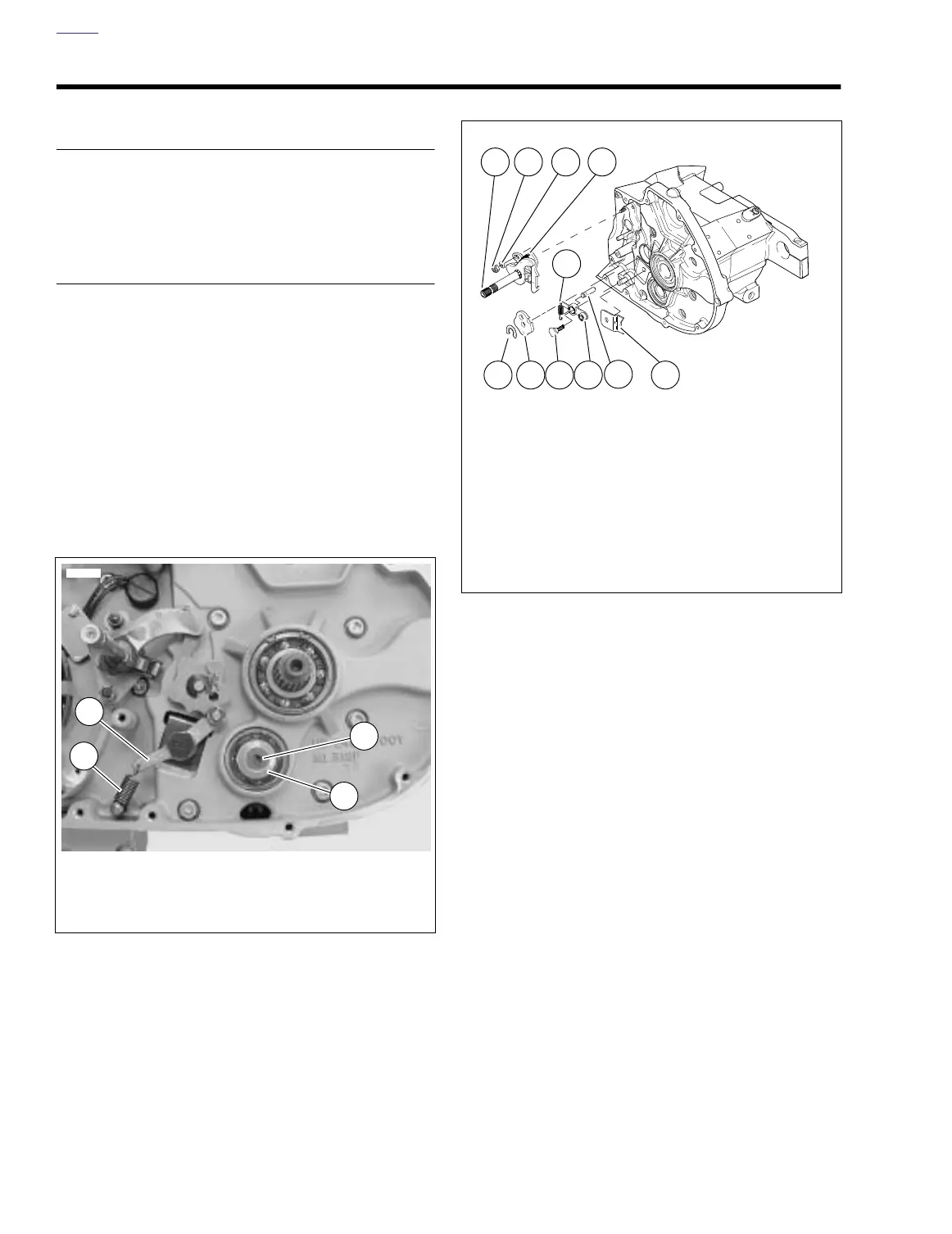
9. See Figure 6-25. Detach spring (11) from groove in post.
10. Remove retaining ring (10) and detent plate (9). Discard
retaining ring (10). You will need to use a
new
retaining
ring for installation.
11. Remove starter. See 5.7 STARTER.
12. See Figure 6-25. Remove two locknuts (2) and washers
(3) which attach shifter shaft assembly (1) to studs at
transmission case. Remove shifter shaft assembly (1).
13. Remove detent screw (8), detent arm (7) and spring (11).
Figure 6-24. Countershaft Retainer
7691
1. Detent roller arm
2. Spring
3. Retention collar
4. TORX screw
2
1
4
3
Figure 6-25. Shifter Shaft Assembly
1. Shifter shaft assembly
2. Locknut (2)
3. Washer (2)
4. Shifter pawl
5. Plate
6. Pin
7. Detent arm
8. Detent screw
9. Detent plate
10. Retaining ring
11. Spring
a0119x6x
321
5
6
78910
11
4