3-8 2007 Buell P3: Engine
HOME
STRIPPING MOTORCYCLE FOR ENGINE SERVICE 3.3
DISASSEMBLY
1. Lift and secure the motorcycle by placing the vehicle on
a lift and anchor rear wheel in place. Raise lift so the top
of the cylinder head is easy to access.
2. Remove seat. See 2.28 SEAT.
11WARNING1WARNING
To prevent accidental vehicle start-up, which could
cause death or serious injury, disconnect negative (-)
battery cable before proceeding. (00048a)
11WARNING1WARNING
Disconnect negative (-) battery cable first. If positive (+)
cable should contact ground with negative (-) cable con-
nected, the resulting sparks can cause a battery explo-
sion, which could result in death or serious injury.
(00049a)
3. Disconnect
both
battery cables, negative cable first. See
7.16 BATTERY.
4. Remove fuel tank. See 7.16 BATTERY.
5. Remove muffler. See 2.20 EXHAUST SYSTEM.
6. Place jack under the motor. Use jack to lower motor.
7. Remove horn. See 7.22 HORN.
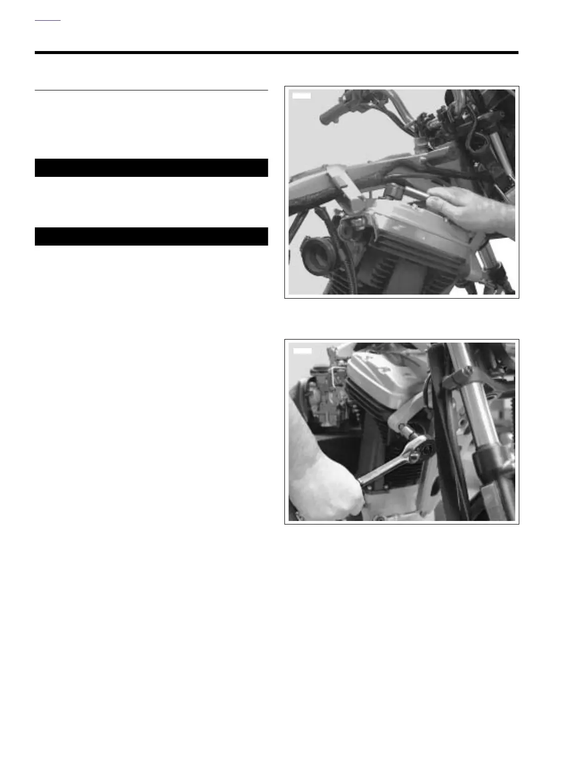
8. See Figure 3-1. Remove crankcase breather hose and
crankcase breather from rocker box grommet.
IMPORTANT NOTE
See Figure 3-2. Do not attempt to remove isolator mount
from cylinder head. Isolator mount is an integral compo-
nent and is not meant to be removed unless absolutely
necessary. Repeated removals and installations will
damage cylinder head threads.
NOTES:
●
Remove the isolator mount ONLY to replace the engine,
cylinder head or servicing of exhaust valve components.
For all other disassembly and servicing do not remove
mount from cylinder head.
●
Proceed to step 9. for engine removal, cylinder head
replacement or complete cylinder head servicing includ-
ing exhaust valve components.
●
For all other disassembly and related servicing proce-
dures proceed to step 10.
9. See Figure 3-2. Remove the two mounted cylinder head
bolts from the front isolator/engine bracket marked “DO
NOT REMOVE”. See note above.
NOTES
●
For top end service proceed to step 11.
●
For engine removal proceed to step 12.
Figure 3-1. Remove Crankcase Breather Hose
Figure 3-2. Cylinder Head Bolts
7629
7646