6-32 2007 Buell P3: Drive/Transmission
HOME
RIGHT TRANSMISSION CASE BEARINGS 6.10
REMOVAL
NOTE
See Figure 6-46. Refer to Transmission assembly right crank-
case half, for location of items discussed on this page.
1. Remove transmission assembly. See 6.7 TRANSMIS-
SION DISASSEMBLY.
2. See Figure 6-44. Remove main drive 5th gear. Use MAIN
DRIVE GEAR REMOVER AND INSTALLER (Part
No.HD-35316A). See 6.9 MAIN DRIVE GEAR.
3. At outside of case remove seal next to 5th gear bearing
retainer. Remove retaining ring.
4. From inside transmission case drive bearings (5th gear,
countershaft or shifter shaft) out of bores. Carefully tap
bearings free by working around bearing diameter to
keep bearing from skewing.
INSTALLATION
Mainshaft 5th Gear Ball Bearing
1. Locate MAIN DRIVE GEAR REMOVER AND
INSTALLER (Part No. HD-35316-A). See Figure 6-44.
Place cross plate pins in appropriate holes in transmis-
sion case.
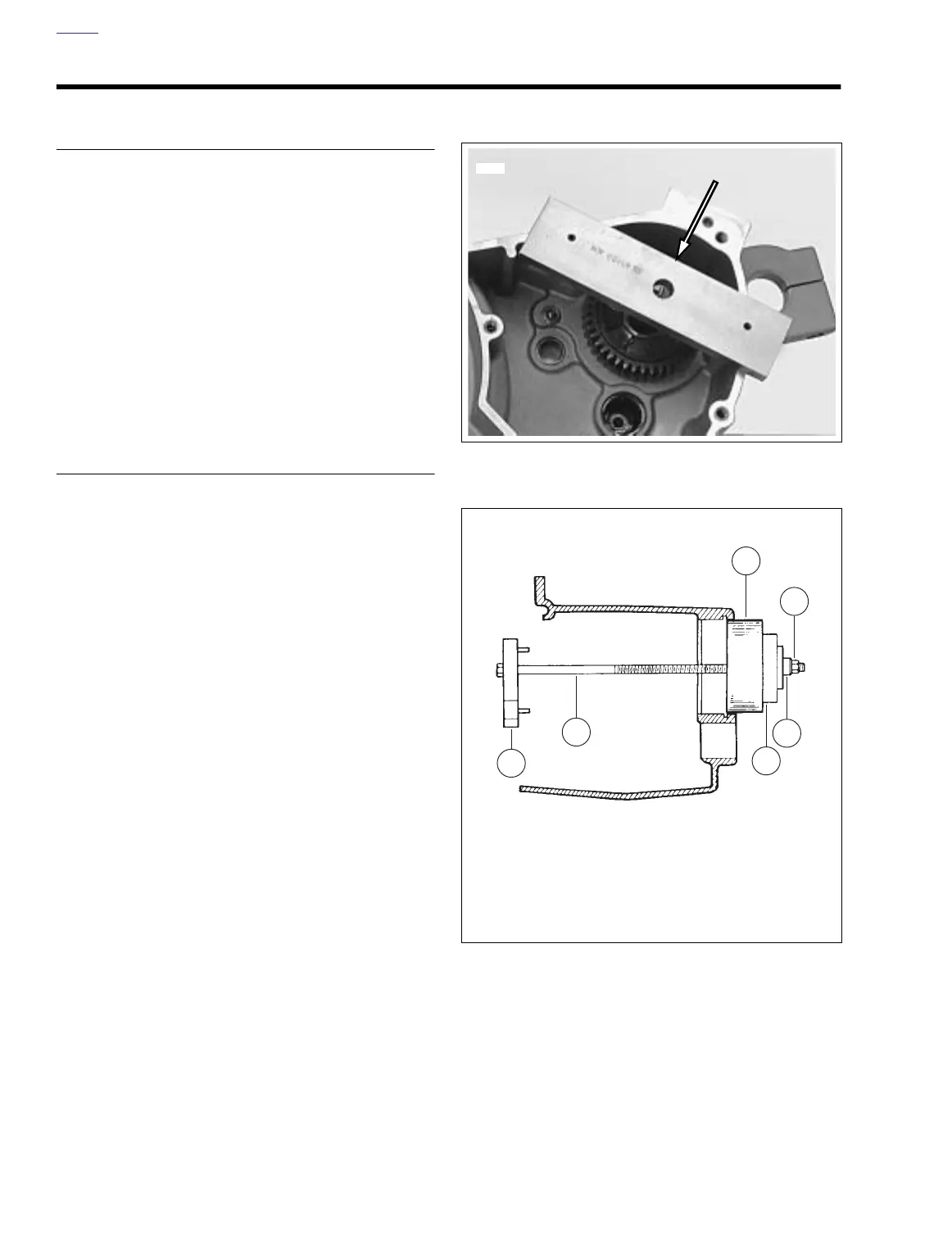
2. See Figure 6-45. Insert bolt (2) through cross plate (1),
new
bearing (3), driver (4) and thrust bearing (5). Thread
nut (6) on end of bolt. Tighten nut carefully until bearing
is started in bore squarely. Tighten nut (6) until bearing is
seated against shoulder in bore.
3. At outside of case install beveled retaining ring in groove
inside bearing bore with beveled side facing outside.
4. Lubricate bearing with FORMULA+ Primary/Transmis-
sion Lubricant.
Countershaft Needle Bearing
1. Find a suitable bearing driver 1-1/4 in. (31.75 mm) in
diameter.
2. From the outside of the case place the needle bearing
open end first next to the bearing bore. Hold the driver
squarely against the closed end of the bearing and tap
the bearing into place. The bearing is properly positioned
when it is driven inward flush or 0.030 in. (0.762 mm)
below the outside surface of the case.
3. Lubricate bearing with FORMULA+ Primary/Transmis-
sion Lubricant.
Shift Drum Needle Bearing
1. Find a bearing driver 0.8125 in. (20.64 mm) in diameter.
2. From the outside of the case place the needle bearing,
open end first, next to the bearing bore. Hold the driver
squarely against the closed end of the bearing and tap
the bearing into place. The bearing is properly positioned
when driven inward flush or 0.030 in. (0.762 mm) below
the outside surface.
3. Lubricate bearing with FORMULA+ Primary/Transmis-
sion Lubricant.
Figure 6-44. Mounting Cross Plate (Part No. B-43983)
Figure 6-45. Installing Mainshaft Ball Bearing
7397
6
5
4
2
1
3
a0125xTx
1. Cross plate
2. Bolt
3. Bearing
4. Driver
5. Thrust bearing
6. Nut