Appendix B: Wiring B-15
HOME
WIRING DIAGRAMS B.8
WIRE COLOR CODES
Wire traces on wiring diagrams are labeled with alpha codes.
Refer to Table B-6.
For Solid Color Wires:
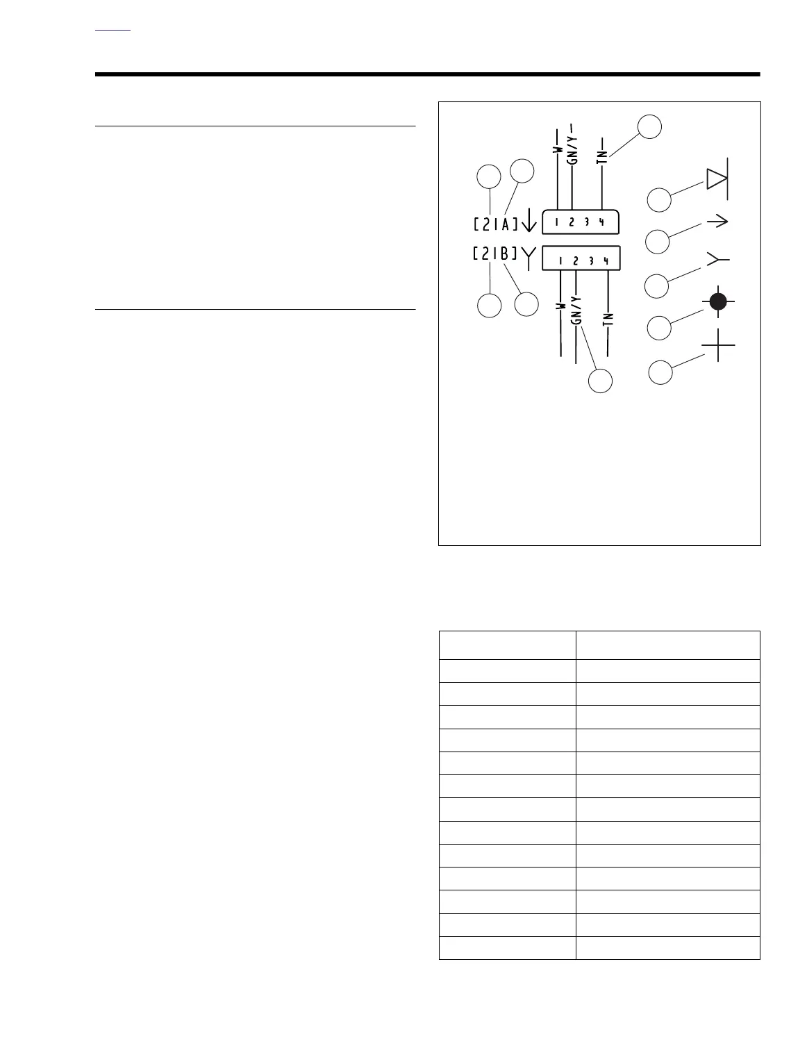
See Figure B-17. The alpha code
identifies wire color (3).
For Striped Wires:
The code is written with a slash (/)
between the solid color code and the stripe code (4). For
example, a trace labeled GN / Y is a green wire with a yellow
stripe.
WIRING DIAGRAM SYMBOLS
See Figure B-17. On wiring diagrams and in service/repair
instructions, connectors are identified by a number in brack-
ets (1). The letter (2) inside the brackets identifies whether
the housing is a socket or pin housing.
A=Pin:
The letter A after a connector number and/or the pin
symbol (5) identifies a pin housing.
B=Socket:
The letter B after a connector number and/or the
socket symbol (6) identifies a socket housing.
Other symbols found on the wiring diagrams include the sym-
bol for a diode (7), a symbol for a wire-to-wire connection (8)
and a symbol that verifies that no connection (9) between two
wire traces exists.
Figure B-17. Connector/Wiring Diagram Symbols (typical)
Table B-6. Wire Color Codes
Alpha Code Wire Color
BE Blue
BK Black
BN Brown
GN Green
GY Grey
LGN Light Green
O Orange
PK Pink
R Red
TN Tan
V Violet
W White
Y Yellow
1. Connector number
2. Terminal code (A=pin, B=socket)
3. Solid wire color
4. Striped wire color
5. Pin symbol
6. Socket symbol
7. Diode
8. Connection
9. No connection