7-26 2007 Buell P3: Electrical
HOME
STARTER/IGNITION INTERLOCK 7.11
GENERAL
The starter/ignition interlock system is designed to prevent
unintended start-up and/or forward motion of the motorcycle.
One of three conditions must exist to allow operation of the
vehicle:
● Clutch disengaged (lever pulled in)
● Transmission in Neutral
● Sidestand retracted
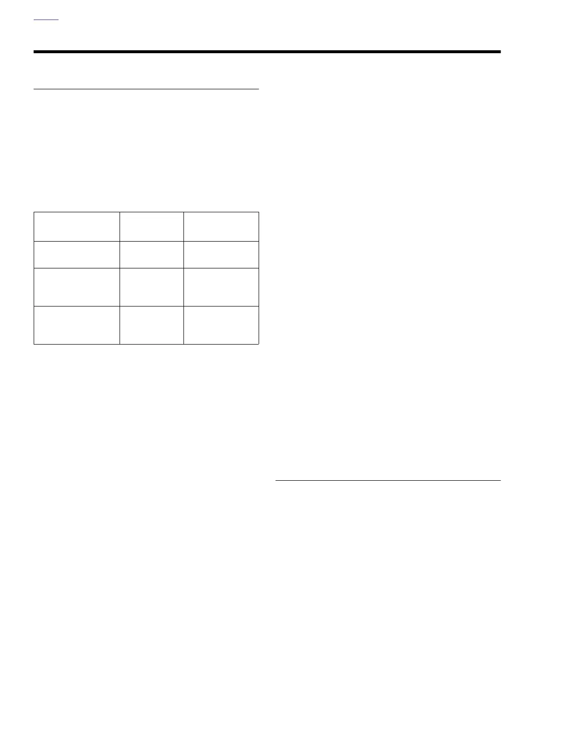
Table 7-19. Voltage At TN/Y Wire At Con-
nector [10B]
Starter Circuit
The starter circuit prevents the motorcycle from being started
unless a ground has been established at the starter relay.
This ground comes from one source.
● By disengaging the clutch (pulling in the clutch lever) and
grounding through the clutch lever switch.
Once the starter circuit is grounded and the starter button
pushed, the starter relay can be energized. The energized
relay then allows the starter motor to crank the engine.
Ignition Circuit
The ignition circuit prevents the motorcycle from operating
unless a ground is established at the system relay. If this
ground is not established, the ignition system will not be
turned on and the motorcycle will not run. Grounds may be
established three ways.
● By retracting the sidestand and grounding through the
sidestand switch. See Ignition Test 1 on following page
to check sidestand switch function.
● By placing the motorcycle in neutral and grounding
through the neutral switch. See Ignition Test 2 on follow-
ing page to check neutral switch function.
● By disengaging the clutch and grounding through the
clutch lever switch. See Ignition Test 3 on page 7-28 to
check clutch switch function.
Note that the ignition circuit is enabled when the transmission
is in gear with the sidestand extended if the clutch is disen-
gaged (clutch lever pulled in). However, if the motorcycle is in
gear with the sidestand extended, and the clutch lever is
released, the ignition ground is lost and the ignition system is
turned off. This system will prevent vehicle operation if for-
ward motion is attempted with the sidestand down.
See 7.3 DIAGNOSTIC CHARTS for Ignition Tests.
DIAGNOSTIC NOTES
In the following diagnostic flow charts, the circled numbers
correspond to the diode tests found in the TESTING/
REPLACEMENT section following the Starter/Ignition Inter-
lock System wiring diagram.
Use gray male probe and patch cord from TEST CONNEC-
TOR KIT (Part No. HD-41404) to perform the tests.
CONDITION
SIDESTAND
DOWN
SIDESTAND UP
Clutch Engaged
Transmission in Gear
<1.0V 12V
(Battery Voltage)
Neutral
Battery Voltage
minus 0.7V +/-
0.1V
12V
(Battery Voltage)
Clutch Disengaged
Battery Voltage
minus 0.7V +/-
0.1V
12V
(Battery Voltage)