7-12 2007 Buell P3: Electrical
HOME
THROTTLE POSITION SENSOR (TP SENSOR) 7.4
GENERAL
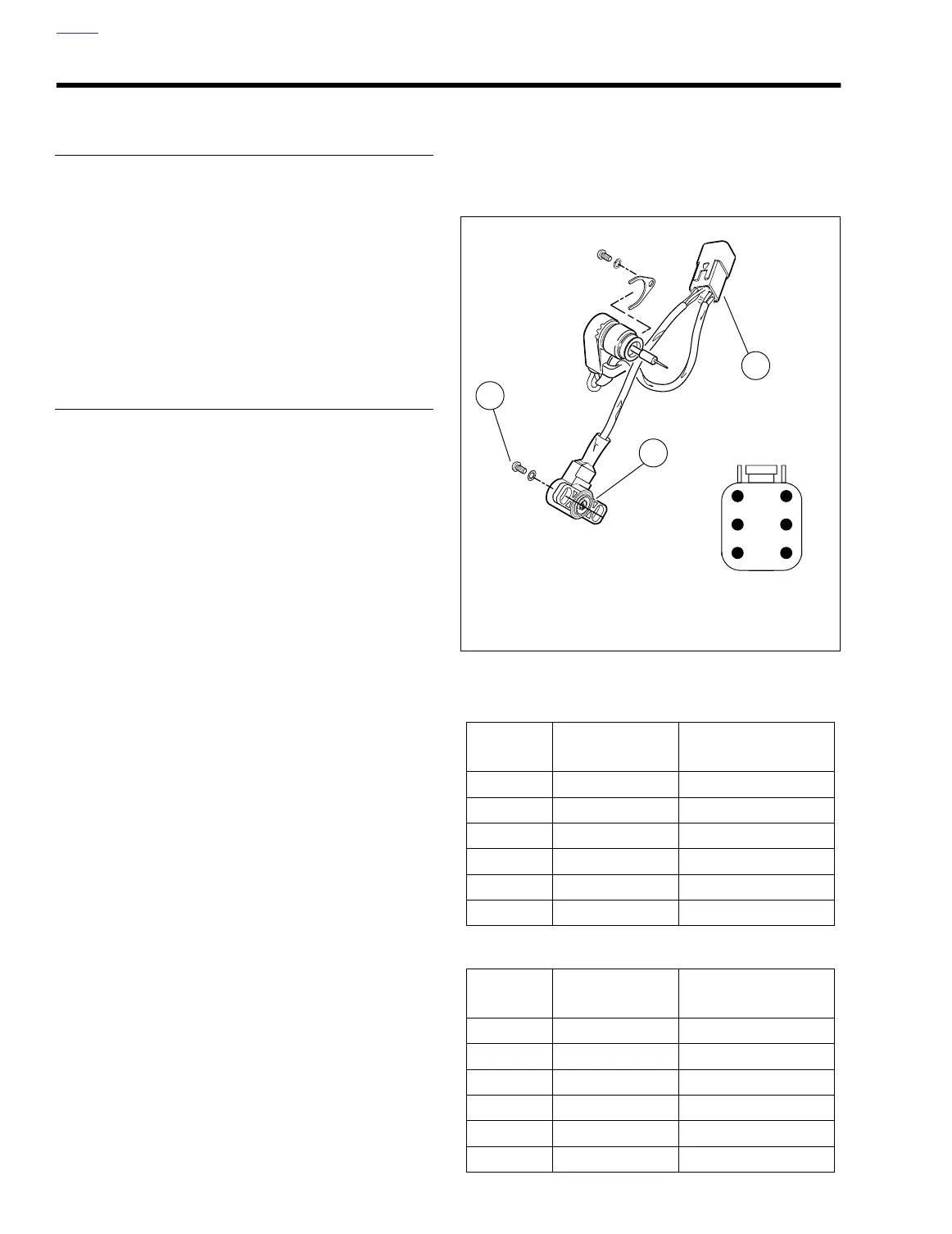
See Figure 7-10. The throttle position sensor voltage deter-
mines which spark advance curve the ignition module
selects. The throttle position sensor (TP Sensor) is located on
the carburetor. The TP Sensor is not repairable. Replace the
unit if it fails.
See 4.6 THROTTLE POSITION SENSOR for information on
replacing the throttle position sensor.
See diagnostic chart on previous page for troubleshooting
information.
CALIBRATION/TESTING
NOTE
To gain access to the Throttle Position Sensor, remove the
carburetor and air cleaner as an assembly. See 4.4 CARBU-
RETOR and 1.17 AIR CLEANER.
1. Adjust throttle position sensor as follows:
a. Back off idle adjustment screw so throttle plate is
fully closed.
b. Completely open and close the throttle by rotating
the throttle control through its full range of motion.
c. Using special TORX bit (Snap-on
®
TTXR20E),
loosen the two tamper-resistant T20 TORX screws
just enough to allow sensor to rotate.
d. Separate connector [88] housings and remove
socket terminal from chamber 3 in connector [88B]
(main wire harness).
e. Install BREAKOUT BOX ADAPTORS (Part No. HD-
42962) and BREAKOUT BOX (Part No. HD-42682)
using black connectors between socket [88B] and
pin [88A] housings.
f. Turn ignition switch to ON. Using a multimeter, mea-
sure voltage between pin 3 (V/W) and pin 5 (BK).
g. Adjust (rotate) throttle position sensor (TPS) until
voltage reading is 0.5V +/- 0.05V.
h. Completely open and close the throttle by rotating
the throttle control through its full range of motion.
Wide Open Throttle (WOT) should not exceed 3.7V
and reading should increase consistently as throttle
is opened. If the voltage reading is erratic or the volt-
age reading at WOT exceeds 3.7V, see Figure 7-10.
for diagnostic testing.
NOTE
After WOT, the TPS reading may not return back to exactly
0.5V +/- 0.05V. To re-check exact TPS voltage reading, turn
cycle key off and on.
i. Tighten TP Sensor mounting screws to 13-23
in-lbs
(2-3 Nm).
2. Install carburetor and air cleaner. See 4.3 AIR
CLEANER.
3. Adjust idle speed. See 1.19 IGNITION TIMING AND
IDLE SPEED ADJUSTMENT.
Figure 7-10. Throttle Position Sensor
Table 7-10. Socket Housing [88B]
CHAMBER
NUMBER
WIRE COLOR FUNCTION
1 Violet/Orange Auto-Enrichener
2 Orange Auto-Enrichener
3 Violet/White TP Sensor Output
4 Violet/White TP Sensor Input
5 Black TP Sensor Ground
6 Not Used
Table 7-11. Pin Housing [88A]
CHAMBER
NUMBER
WIRE COLOR FUNCTION
1 Yellow Auto-Enrichener
2 Yellow Auto-Enrichener
3 Light Blue TP Sensor Output
4 Yellow TP Sensor Input
5 Black TP Sensor Ground
6 Not Used
a0225x7x
1
2
3
4
5
6
[88A]
a0223x7x
1. Connector pin housing [88A]
2. Throttle position sensor
3. Tamper-resistant T20 TORX screws
1
2
3