2007 Buell P3: Electrical 7-55
HOME
HANDLEBAR SWITCHES 7.21
REMOVAL
NOTE
The individual handlebar switches are not repairable.
Replace switch assembly upon switch failure.
Right Side
1. Detach throttle cables.
2. See Figure 7-71. Cut cable strap to access right handle-
bar switch connector [22] behind dash. Detach connector
[22] from wiring harness.
3. Cut as many cable straps as necessary to access brake
switch connector [170]. Detach connector [170] from wir-
ing harness.
Left Side
1. Remove three screws from handlebar switch.
2. Separate switch housings and remove from handlebar.
3. See Figure 7-73. Cut cable strap(s) as necessary to
access left handlebar switch connector [24] and clutch
switch connector [95] behind dash. Detach connector
[24] from wiring harness.
4. Remove connector [95] from clutch switch.
INSTALLATION
Right Side
1. Attach throttle cables to hand control.
2. Position housings on right handlebar by engaging stud
on front housing with hole in handlebar. Fasten housings
with two screws. Tighten to 25-33 in-lbs (2.8-3.7 Nm).
3. See Figure 7-71. Route switch housing wiring harness
between front forks. Attach connector [170] and connec-
tor [22] to wiring harness. Fasten wiring harness behind
dash with new cable straps.
4. Adjust throttle cables. See 1.18 THROTTLE CABLES.
11WARNING1WARNING
Be sure that all lights and switches operate properly
before operating motorcycle. Low visibility of rider can
result in death or serious injury. (00316a)
5. See Figure 7-72. Check handlebar switch for proper
operation. If operation fails, reread procedure and verify
that all steps were performed.
a. Turn ignition key switch to IGN.
b. Start motorcycle.
c. Turn ignition key switch to OFF.
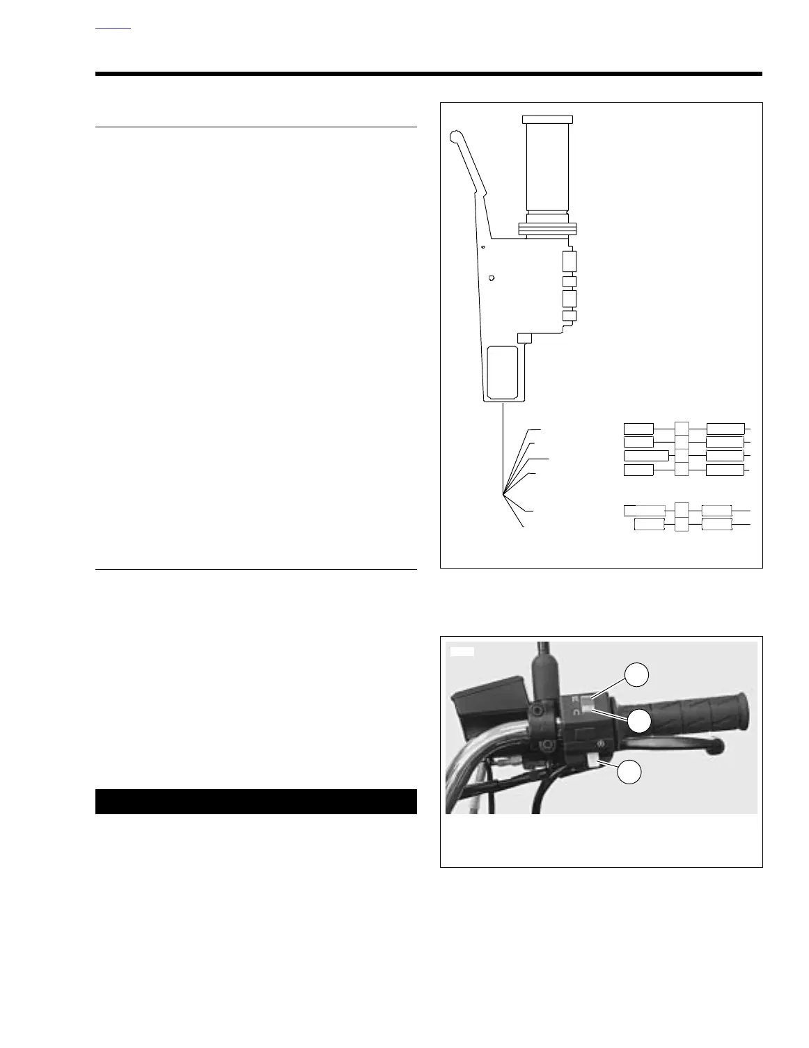
Figure 7-71. Right Handlebar Switch Connection [22] and
Brake Switch Connection [170]
Figure 7-72. Right Handlebar Switches
IGN MODULE
FROM [3]
GN/BK
W/R
W/BK
W/BK
TO STARTER
IGN POWER
TO STOPLIGHT
ACC POWER
1
2
1
3
2
4
O
W/BK1
R/YR/Y
Y/R
BE
BK/R
GY/O
a0259x7x
[22]
[170]
7809
1. Ignition OFF
2. Ignition ON
3. Electric starter switch
2
1
3