B-14 Appendix B: Wiring
HOME
SPLICING WIRE LEADS
NOTE
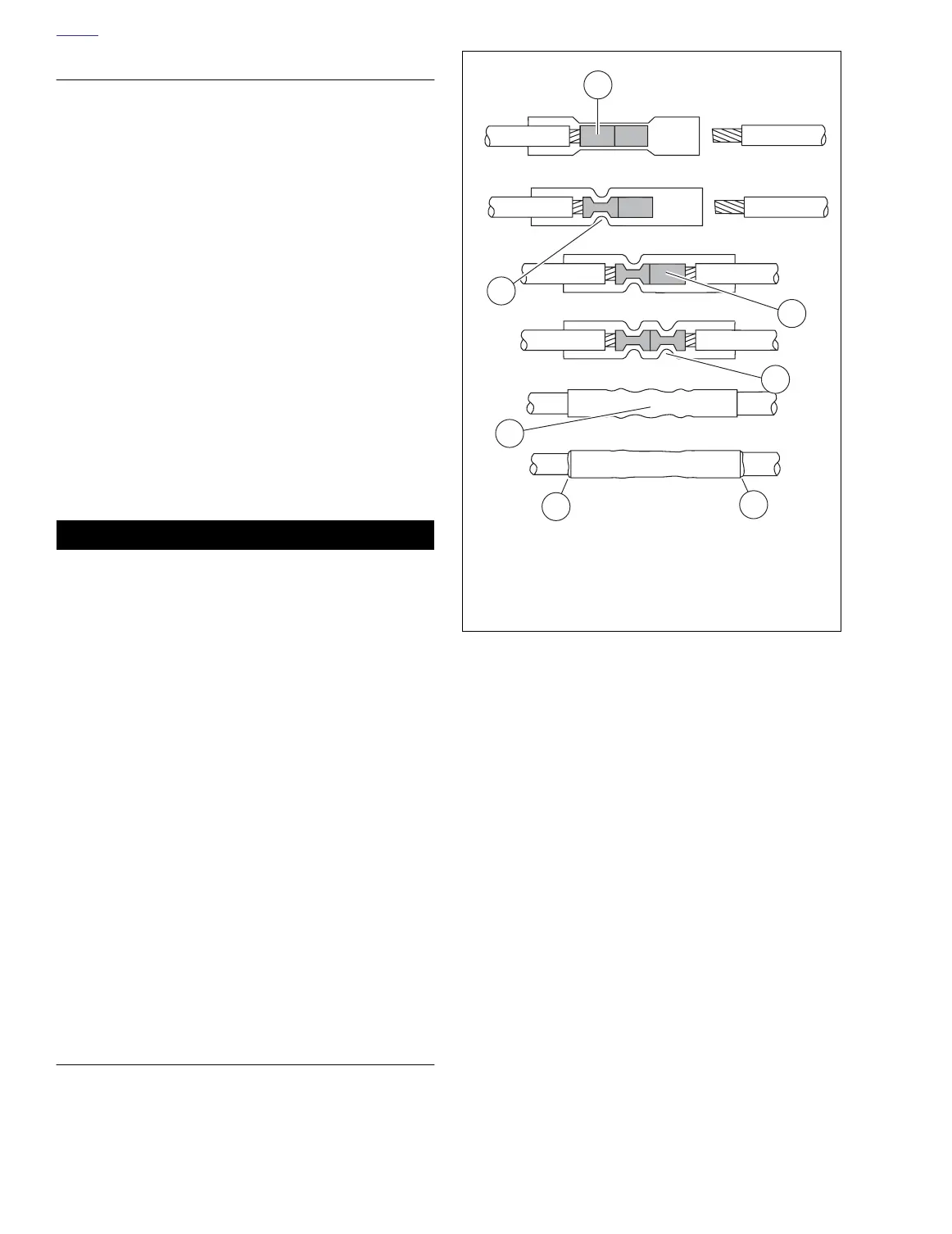
See Figure B-16.
T
he connector is crimped twice - one side
and then the other.
1. See Figure B-15. Open the Packard Crimping Tool (HD-
38125-8) ratchet by squeezing the handles closed.
2. Match the connector color to the wire gauge crimp die in
the jaws and insert one end of the sealed connector.
3. Gently squeeze the handles until the connector is held in
the jaws.
4. See Figure B-16. Feed the stripped end of a wire into the
connector until the wire stops inside the metal insert (1).
5. Squeeze the handles tightly closed to crimp the lead in
the insert (2). The tool automatically opens when the
crimping is complete.
6. Slide the connector to the other half of the metal insert.
Insert the stripped wire lead (1) until it stops, and crimp
the lead in the insert (2).
11WARNING1WARNING
Be sure to follow manufacturer's instructions when
using the Ultra-Torch UT-100 or any other radiant heating
device. Failure to follow manufacturer's instructions can
cause a fire, which could result in death or serious injury.
(00335a)
●
Avoid directing heat toward any fuel system compo-
nent. Extreme heat can cause fuel ignition/explosion
resulting in death or serious injury.
●
Avoid directing heat toward any electrical system
component other than the connectors on which heat
shrink work is being performed.
●
Always keep hands away from tool tip area and heat
shrink attachment.
7. Use an Ultra-Torch (HD-39969), or a Heat Gun (HD-
25070) with a Heat Shield Attachment (HD-41183), to
heat the connector from the center of the crimp (3) out to
each end.
NOTE
It is acceptable for the splice to rest against the heat shrink
tool attachment.
INSPECT SEAL
See Figure B-16. Allow the splice to cool and inspect the
seal. The insulation should appear smooth and cylindrical.
Melted sealant will have extruded out the ends (4) of the insu-
lation.
Figure B-16. Sealed Splice Connector
1
1
4
2
2
4
3
f2525x1x
1. Wire lead in metal insert
2. Crimped metal insert
3. Center of crimp
4. Melted sealant