Appendix B: Wiring B-13
HOME
SEALED SPLICE B.3
GENERAL
Splice connectors and several OE ring terminal connectors
use heat shrink covering to seal the connection.
PREPARE THE WIRE LEADS
NOTE
If adjacent wires are to be spliced, stagger the splices so that
the sealed splice connectors will not touch each other but are
located at different positions along the length of the wires.
1. Identify (use a shop gauge) the gauge of the wire.
2. Match the wire gauge to a sealed splice connector by
color and part number. Refer to Table B-5.
3. Using a wire stripper, cut and strip a length of insulation
off the wire ends. Refer to Table B-5. for the strip length.
NOTE
If any copper wire strands are cut off of the wire core, trim the
end and strip the wire again in a larger gauge stripper.
PART NO. SPECIALTY TOOL
HD-38125-8 Packard crimping tool
HD-39969 Ultra-torch
HD-25070 Heat gun
HD-41183 Heat shield attachment
Table B-5. Sealed Splice Connectors
Wire Gauge
Connector
Color
Connector
Part No.
Strip Length
18-20
(0.5-0.8 mm
Red 70585-93 3/8 in.
(9.5 mm)
14-16
(1.0-2.0 mm)
Blue 70586-93 3/8 in.
(9.5 mm)
10-12
(3.0-5.0 mm)
Yellow 70587-93 3/8 in.?
(9.5 mm)
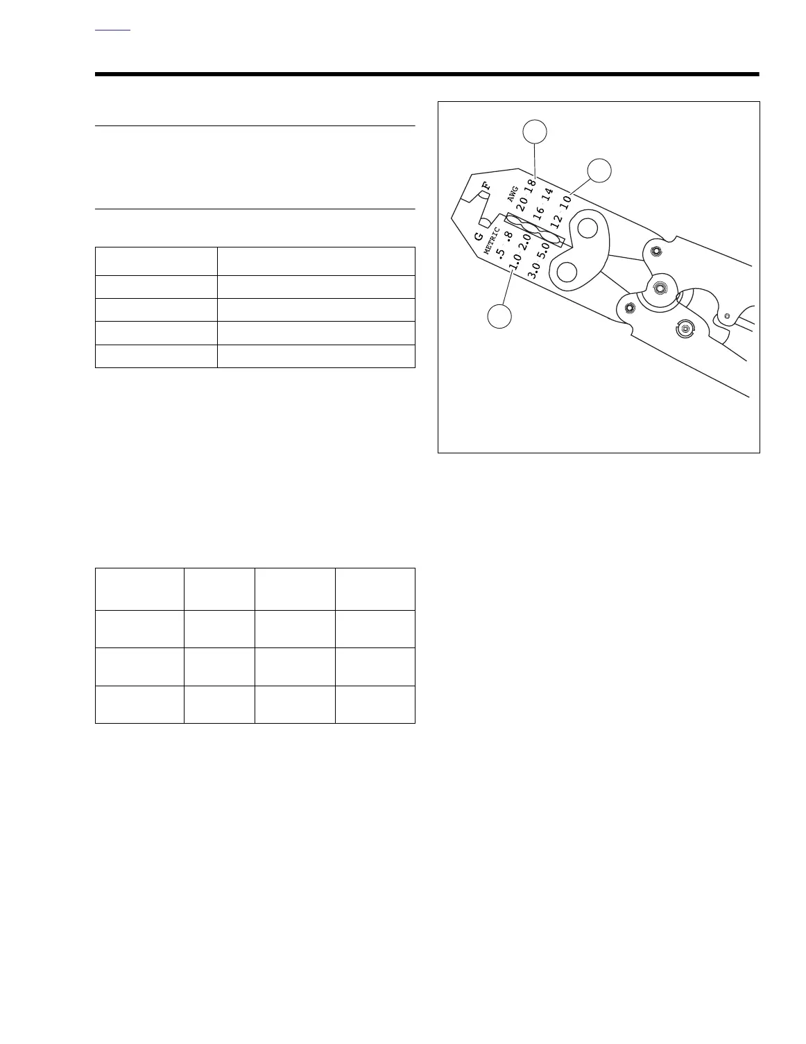
Figure B-15. Packard Crimping Tool (HD-38125-8)
1. Red connector die
2. Blue connector die
3. Yellow connector die