B-12 Appendix B: Wiring
HOME
DEUTSCH STANDARD TERMINAL B.4
PREPARE WIRE LEAD
1. Use a shop gauge to determine gauge of wire lead.
2. Strip lead removing 5/32 inch (4.0 mm) of insulation.
CRIMP TERMINAL TO LEAD
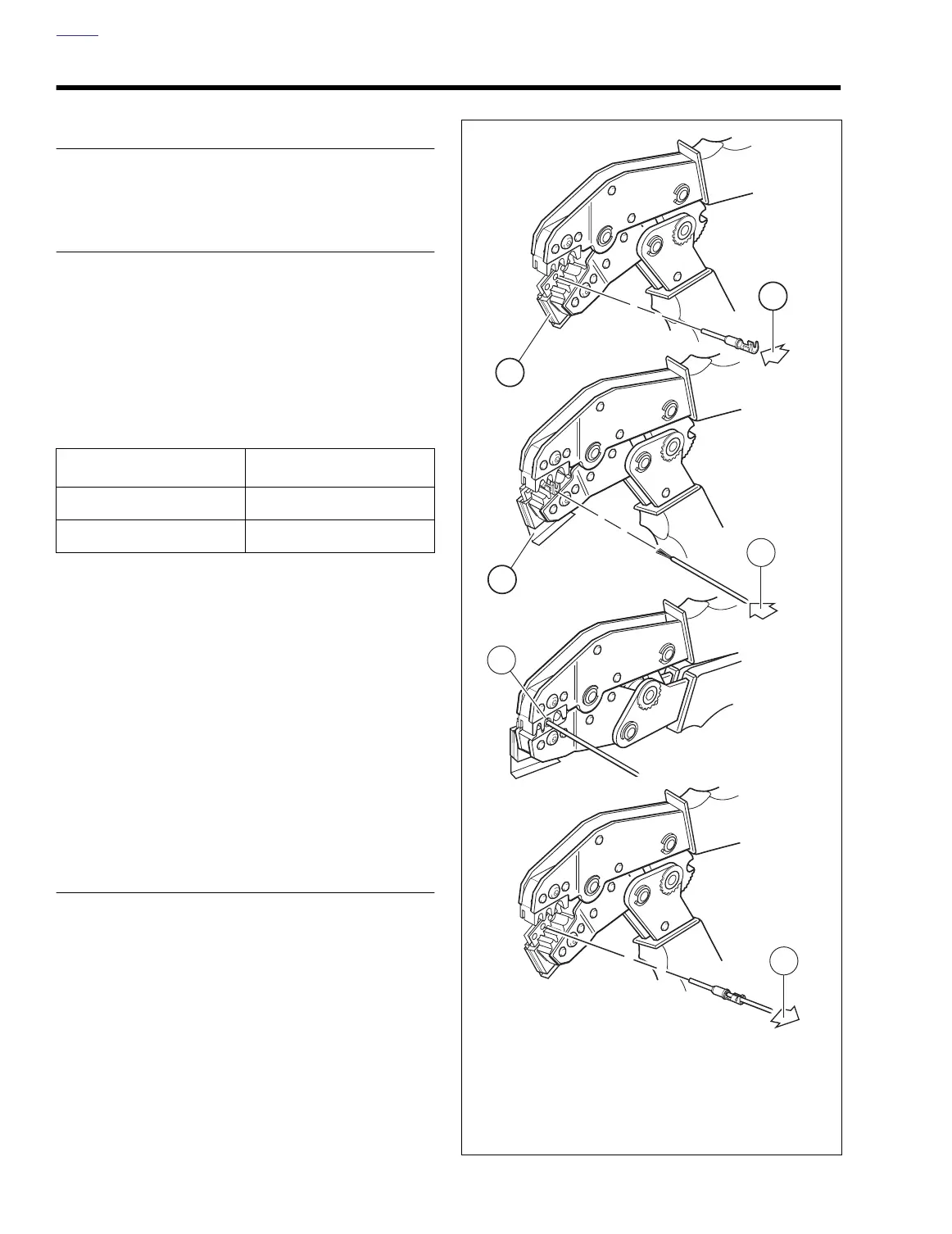
1. See Figure B-14. Squeeze the handles of the DEUTSCH
TERMINAL CRIMP TOOL (HD-39965) to open the jaws.
Push the locking bar (1) up.
2. Insert (2) terminal (socket/pin) through hole of the lock-
ing bar, so that the rounded side of the contact barrel
rests in the die (concave split level area) with the crimp
tails facing upward. To match the wire gauge to the crimp
tool die, refer to Table B-4.
3. Release locking bar to lock terminal in die.
NOTE
If the crimp tails are slightly out of vertical alignment, the
crimp tool automatically rotates the terminal so that the tails
face straight upward. When positioned, the locking bar fits
snugly in the space between the contact band and the core
crimp tails.
4. Insert stripped wire core between crimp tails until ends
make contact with locking bar. Verify that wire is posi-
tioned so that short pair of crimp tails squeeze bare wire
strands, while long pair folds over the insulation.
5. Squeeze handle of crimp tool until tightly closed. Tool
automatically opens after the terminal is crimped.
6. Raise locking bar up and remove wire lead and terminal.
INSPECT CRIMP
Inspect the wire core and insulation crimps. Distortion should
be minimal.
Table B-4. Wire Gauge to Die
Wire Gauge (AWG) Crimp Tool Die
20 Front
16-18 Middle
Figure B-14. Crimping a Deutsch Standard Terminal
2
5
4
6
1
3
f2501x1x
1. Open jaws and raise locking bar
2. Insert terminal in locking bar
3. Release locking bar to lock terminal in die
4. Insert stripped lead
5. Squeeze crimper
6. Raise locking bar and remove terminal