Appendix B: Wiring B-11
HOME
Install Pin Terminals
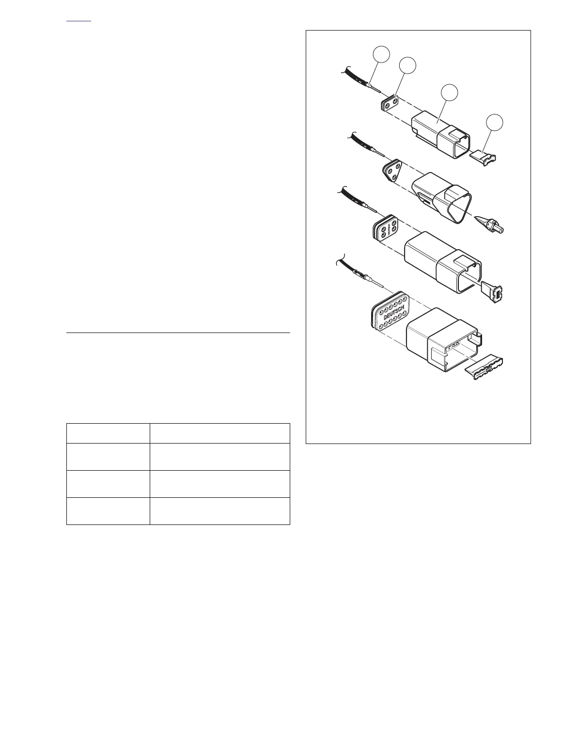
1. See Figure B-13.
Fit wire seal (1) into back of pin hous-
ing (2).
2. Grasp wire lead approximately 1 in. (25.4 mm) behind
the pin terminal (3). Gently push pin through holes in
wire seal into its respective numbered chamber until it
“clicks” in place.
NOTE
A tug on the wire lead will confirm that a pin is locked in place.
3. Insert tapered end of secondary locking wedge (5) into
pin housing and press down until it snaps in place.
NOTES
●
The wedge fits in the center groove of the pin housing
and holds the terminal latches tightly closed.
●
See Figure B-10. While rectangular wedges do not
require a special orientation, the conical secondary lock-
ing wedge of the 3-place connector must be installed
with the arrow (2) pointing toward the external latch.
●
If the secondary locking wedge does not slide into the
installed position easily, verify that all terminals are fully
installed in the pin housing. The lock indicates when ter-
minals are not properly installed by not entering its fully
installed position.
TERMINAL CRIMPS
Refer to Table B-3. Identify which of the types of Deutsch ter-
minals are used with the connector and follow the corre-
sponding crimping instructions.
Table B-3. Deutsch Terminal Crimping
Instructions: 2007 Buell Blast
TYPE CRIMPING INSTRUCTIONS
Standard
(with crimp tails)
B.4 DEUTSCH STANDARD TER-
MINAL
Mini-Deutsch
(with crimp tails)
N/A
Solid barrel
(without crimp tails)
N/A
Figure B-13. 2, 3, 4 and 12 Place Pin Housings
1. Wire seal
2. Pin housing
3. Pin terminal
4. Locking wedge