Appendix B: Wiring B-9
HOME
WIRE TERMINALS
Remove Socket Terminals
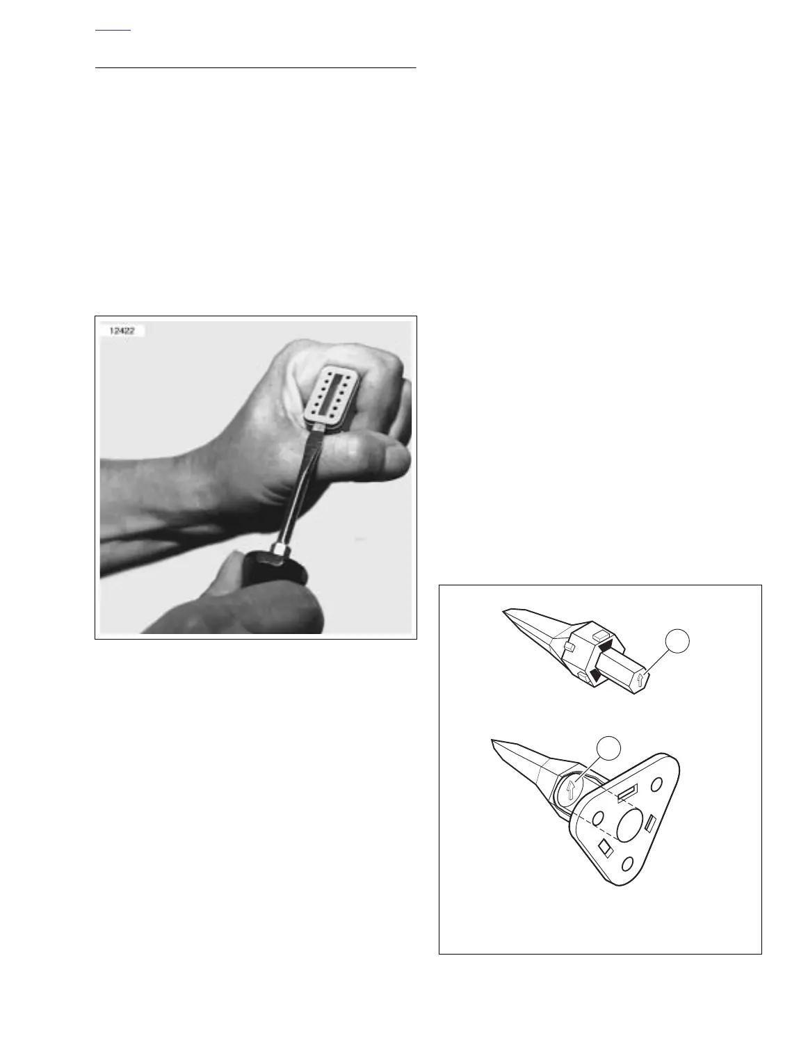
1. See Figure B-9. Insert a small screwdriver between the
socket housing and locking wedge in-line with the groove
(in-line with the pin holes if the groove is absent). Turn
the screwdriver 90 degrees to pop the wedge up and
remove the secondary locking wedge.
2. Use a pick or small screwdriver to depress terminal
latches inside socket housing and back out sockets
through holes in rear wire seal. See Figure B-12.
NOTE
If wire leads require new terminals, go to TERMINAL
CRIMPS.
Install Socket Terminals
1. Match wire lead color to connector cavity.
2. See Figure B-11. Fit rear wire seal (1) into back of socket
housing (2), if removed.
3. Grasp wire lead approximately 1 in. (25.4 mm) behind
the socket terminal (3). Gently push socket through hole
in wire seal into its chambers until it “clicks” in place.
4. A tug on the wire will confirm that it is properly locked in
place.
NOTE
Seal plugs (6) are installed through the wire seals of unused
chambers. If removed, seal plugs must be replaced to seal
the connector.
5. Install internal seal (4) on lip of socket housing, if
removed.
6. Insert tapered end of secondary locking wedge (5) into
socket housing and press down until it snaps in place.
The wedge fits into the center groove within the socket
housing and holds the terminal latches tightly closed.
NOTES
●
See Figure B-10. While rectangular wedges do not
require a special orientation, the conical secondary lock-
ing wedge of the 3-place connector must be installed
with the arrow (1) pointing toward the external latch.
●
If the secondary locking wedge does not slide into the
installed position easily, verify that all terminals are fully
installed in the socket housing. The lock indicates when
terminals are not properly installed by not entering its
fully installed position.
Figure B-9. Remove Secondary Locking Wedge
Figure B-10. 3-Place Locking Wedges
1. Arrow on socket locking wedge
2. Arrow on pin locking wedge