B-8 Appendix B: Wiring
HOME
DEUTSCH B.9
GENERAL
Deutsch connectors are colored coded for location purposes.
Those connectors associated with
left
side accessories, such
as the front and rear
left
turn signals, are
gray
. All other con-
nectors, including those associated with right side accesso-
ries, are black.
NOTE
A Deutsch Connector Service Kit (HD-41475) contains a
selection of wire seals, internal seals, seal plugs, secondary
locking wedges, attachment clips and socket/pin terminals.
Also included is a compartmented storage box, carrying case
and pick tool (HD-41475-100) used for the removal of all
types of locking wedges.
PIN AND SOCKET HOUSINGS
Separate Housings
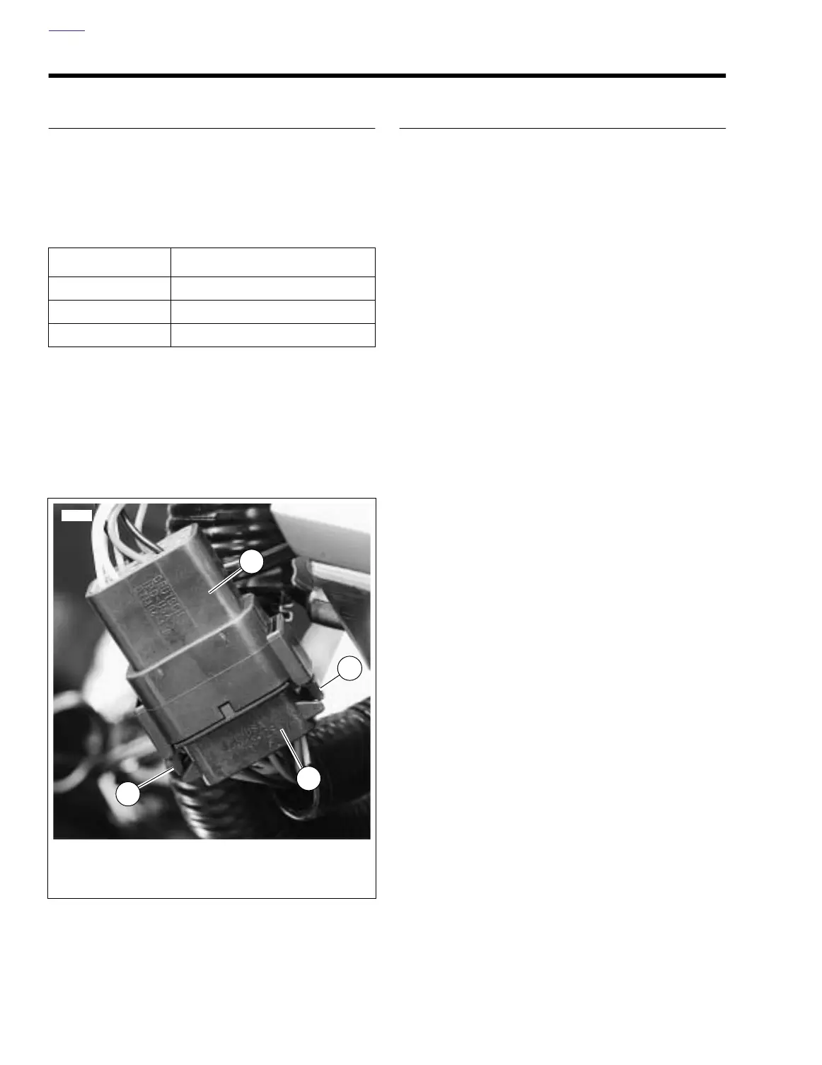
See Figure B-8. To separate the connector halves, depress
the external latch(es) (1) on the socket housing (2) while
rocking the pin (3) and socket housings.
NOTES
●
Generally, the socket housing is found on the accessory
side, while the pin housing is plumbed to the wiring har-
ness.
●
Two-, three-, four- and six-place Deutsch connectors
have one latch on the connector.
●
Eight- and twelve-place connectors have a latch on each
side. Simultaneously press both latches to separate the
connector.
Mate Housings
1. Align the connectors to match the wire lead colors.
For One External Latch:
Two-, three-, four- and six-
place Deutsch connectors have one external latch on the
socket half of the connector. To fit the halves of the con-
nector together, the latch on the socket side must be
aligned with the latch cover on the pin side.
For Two External Latches:
(8-place and 12-place) Align
the tabs on the socket housing with the grooves on the
pin housing.
2. Insert socket housing into pin housing until it snaps or
clicks into place.
For Two External Latches:
(8-place and 12-place) If
latches do not click (latch), press on one side of the con-
nector until that latch engages, then press on the oppo-
site side to engage the other latch.
3. If necessary, fit the attachment clip to the pin housing.
4. Place large end of slot on attachment clip over T-stud on
frame. Push assembly forward to engage small end of
slot.
PART NO. SPECIALTY TOOL
HD-42879 Electrical crimp tool
HD-41475 Deutsch terminal repair kit
HD-38125-7 Packard terminal crimper
Figure B-8. Deutsch Electrical Connector
1. External latch
2. Socket housing
3. Pin housing
3
1
1
2
12424