3-9
20. See Figure 3-3. Remove isolator bolt (7) and lockwasher
(6) on each side.
21. Slowly raise floor hoist until rubber isolators (5) can be
removed. Frame will rise while engine remains secured
to lift by crating strap.
NOTE
Rubber isolators align with a frame mounted metal pin.
22. Raise frame and walk forward over and away from the
engine.
23. If necessary, remove rear swingarm. See SWINGARM in
Section 2.
24. If necessary, detach swingarm mount block from power-
train by removing bolts (3, 4), washers and locknuts.
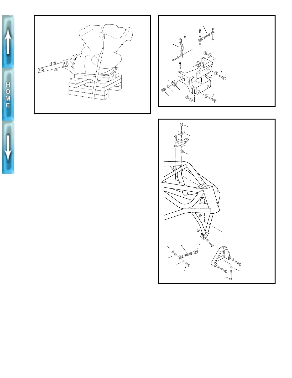
Figure 3-2. Supporting the Engine
b0251x3x
Crating
strap
Figure 3-3. Rear Tie Bar Assembly
Figure 3-4. Front Tie Bar Assembly
1. Ground strap
2. Rear isolator
3. Swingarm mount
block bolts
(2, upper)
4. Swingarm mount
block bolts
(2, lower)
5. Rubber isolator (2)
6. Lockwashers (2)
7. Isolator bolts (2)
b0202x3x
2
1
7
5
3
4
6
b0201x3x
1. Front tie bar
2. Spacer
3. Washer
4. Lockwasher
5. Tie bar bolt
6. Front isolator bol
7. Washer (2)
8. D-washer
9. Nut
1
6
7
7
8
9
2
3
4
5