3-8
STRIPPING MOTORCYCLE FOR ENGINE REPAIR
DISASSEMBLING ENGINE FOR
CYLINDER HEAD REPAIR
1. Lift and secure the motorcycle.
a. Place vehicle on a lift and anchor front wheel in
place. Raise lift so the top of the cylinder head is
easy to access.
b. Raise rear wheel off lift using REAR WHEEL SUP-
PORT STAND (Part No. B-41174).
1
WARNING
To avoid accidental start-up of vehicle and possible per-
sonal injury, disconnect the battery cables before pro-
ceeding. Always disconnect the negative cable first. If
the positive cable should contact ground with the nega-
tive cable installed, the resulting sparks may cause a bat-
tery explosion producing personal injury.
1
CAUTION
Hold battery cable when loosening battery terminal hard-
ware. Failure to hold cable may cause battery damage.
2. Disconnect both battery cables, negative cable first.
3. Remove seat and fuel tank. See FUEL TANK in Section 4.
4. Remove air cleaner assembly. See AIR CLEANER,
REMOVAL in Section 4.
5. Remove exhaust header. See EXHAUST SYSTEM in
Section 2.
6. Remove carburetor and manifold. See CARBURETOR,
REMOVAL in Section 4.
7. If removing front cylinder, remove ignition coil and horn.
See IGNITION COIL in Section 7.
8. Disconnect spark plug cables.
NOTE
At this stage, the lower rocker boxes, the cylinder heads and
the cylinders may be removed. See CYLINDER HEAD on
page 3-11.
REMOVING ENGINE CRANKCASE
OR COMPLETE ENGINE
1. Perform the steps listed above.
2. Remove tail section. See TAIL SECTION, REMOVAL in
Section 2.
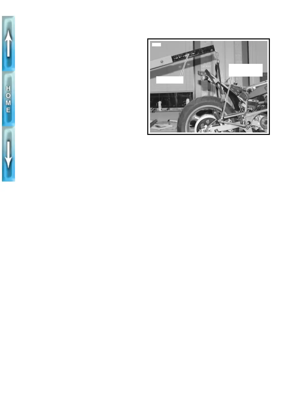
3. See Figure 3-1. Place a floor hoist behind the lift. Attach
straps to frame and hoist. Raise hoist until straps tighten.
4. Detach clutch cable from handgrip.
5.
Remove REAR FENDER/LOWER BELT GUARD and
SPROCKET COVER. See Section 2.
6. Remove rear caliper. See REAR BRAKE CALIPER in
Section 2.
7. Detach belt from rear sprocket and remove rear wheel.
See REAR WHEEL in Section 2.
8. Drain oil tank and remove oil filter. See ENGINE LUBRI-
CATION SYSTEM in Section 1.
9. Disconnect wire to oil pressure signal light switch. See
OIL PRESSURE SIGNAL LIGHT SWITCH on page 3-31.
10. Detach feed, vent and return hoses from oil tank. See
OIL TANK on page 3-30.
11. Remove both rider footrests from frame. See FOOT-
RESTS in Section 2.
12. Remove rear shock mounting bolt (metric) from swing-
arm. Allow rear shock to hang from front mount.
13. Disconnect wiring. See Section 7.
a. Disconnect neutral switch wire from crankcase.
b. Unplug ignition timer plate wires from wiring har-
ness.
c. Disconnect 18-gauge green wire from starter motor.
d. Disconnect regulator/rectifier from the alternator sta-
tor at the plug near the regulator. See VOLTAGE
REGULATOR in Section 7.
e. Disconnect V.O.E.S. wire from ignition module.
14. Remove muffler. See EXHAUST SYSTEM in Section 2.
15. See Figure 3-2. Place a wooden cradle underneath the
crankcase.
16. Place a crating strap between the engine cylinders and
around the lift. Tighten crating strap until snug.
17. See Figure 3-3. Remove engine ground strap (1) from
swingarm mount block.
18. Detach tie bars from frame mounts.
a. Remove rear tie bar using a swivel socket.
b. See Figure 3-4. Remove front tie bar (1) and clutch
cable clamp.
19. Remove front isolator bolt (6), nut (9), D-washer (8) and
washers (7).
Figure 3-1. Floor Hoist
Attach straps
to frame
5673
Floor hoist