3-63
15. Assemble crankcase halves together. See Figure 3-65.
Install hardware to secure crankcase halves. Tighten 1/4-
in. fasteners to 70-110 in-lbs (7.9-12.4 Nm), and 5/16-in.
fasteners to 15-18 ft-lbs (20-24 Nm).
16. See Figure 3-68. Lubricate pinion shaft bearing (11) with
engine oil. Slip bearing (11) on pinion shaft and into outer
race in right crankcase. Install new retaining ring (10) in
groove of pinion shaft bearing inner race (12).
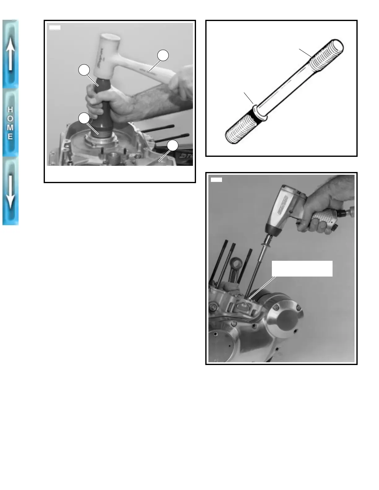
17. See Figure 3-93. The cylinder studs have a shoulder at
the lower end.
18. Pack clean towels into crankcase opening.
19. Place a steel ball into a head bolt, then place the
unpainted end of the stud into the head bolt.
20. See Figure 3-94. Install the stud in the crankcase with
the shoulder end down. Tighten to 10 ft-lbs (13.6 Nm).
21. See Figure 3-65. Install crankcase in chassis using hard-
ware shown.
22. Install transmission mainshaft sprocket. See TRANSMIS-
SION INSTALLATION AND SHIFTER PAWL ADJUST-
MENT in Section 6.
23. Install starter. See STARTER, INSTALLATION in Section 5.
24. Install primary drive components, clutch and clutch
release mechanism. See PRIMARY DRIVE/CLUTCH in
Section 6.
25. Apply two or three drops of LOCTITE THREADLOCKER
262 (red) on threads of sprocket shaft. Tighten front
sprocket nut to 150-165 ft-lbs (203-224 Nm).
NOTE
Be sure to refill transmission with lubricant. See CLUTCH,
TRANSMISSION FLUID in Section 1.
26. Install transmission. See TRANSMISSION INSTALLA-
TION AND SHIFTER PAWL ADJUSTMENT in Section 6.
Figure 3-92. Install Bearing Seal/Spacer
1. Crankcase
2. Rubber mallet
3. Driver handle
4. Seal/spacer driver
3
4598a
4
2
1
Figure 3-93. Cylinder Studs
Figure 3-94. Install Cylinder Stud
b0066x3x
Shoulder
Install this
end up
Install cylinder studs
shoulder end down
3531a