5-12
Solenoid Hold-in Test
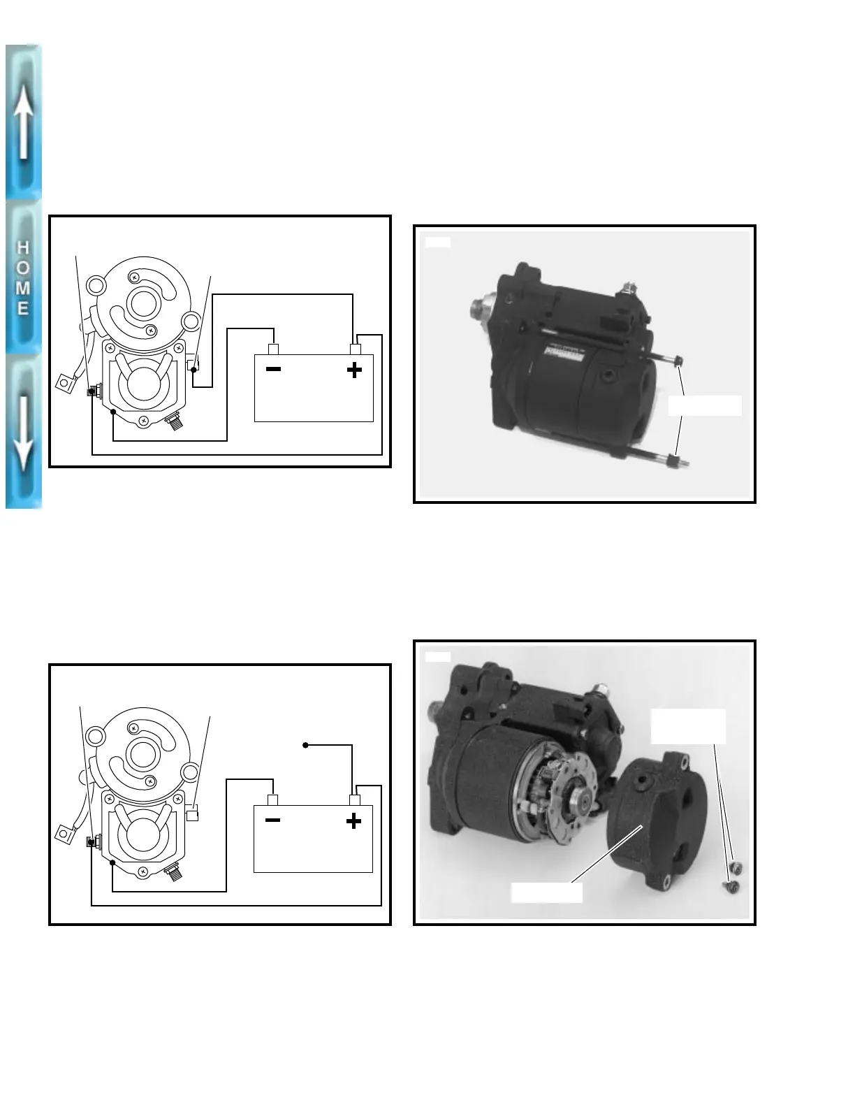
See Figure 5-10. With test leads still connected in the manner
specified in the previous SOLENOID PULL-IN TEST,
discon-
nect solenoid “C” terminal/battery negative test lead at
battery negative end only; reconnect loose end of this
test lead to battery positive, instead.
If pinion remains in
pull-in position, solenoid is working properly. If pinion does
not remain in pull-in position, solenoid should be replaced.
Solenoid Return Test
See Figure 5-11. With test leads still connected in the manner
specified at the end of the previous SOLENOID HOLD-IN
TEST,
disconnect solenoid “50” terminal/battery positive
test lead at either end.
If pinion returns to its original posi-
tion, the solenoid is working properly. If pinion does not return
to its original position, solenoid should be replaced.
DISASSEMBLY, INSPECTION
AND REPAIR
1. See Figure 5-14. Remove field wire (22).
2. See Figure 5-12. Remove thru-bolts.
3. See Figure 5-13. Remove two end cover screws, O-rings,
and end cover.
Figure 5-10. Hold-In Test
Figure 5-11. Return Test
Battery
b0162x5x
“C” terminal
“50” terminal
Battery
b0163x5x
“C” terminal
“50” terminal
Figure 5-12. Removing the Thru-Bolts
Figure 5-13. Removing End Cover
4860
Thru-bolts
3548a
End cover
End cover
screws (2)
5