EasyManuals Logo

Buell S1 Lightning User Manual

Buell S1 Lightning
371 pages
To Next Page IconTo Next Page
To Previous Page IconTo Previous Page
Page #244 background imageLoading...
Page #244 background image
5-18
STARTER SOLENOID
GENERAL
See Figure 5-25. The starter solenoid is a switch that is
designed to open and close the starting circuit electromagnet-
ically. The switch consists of contacts and a winding around a
hollow cylinder containing a movable plunger.
DISASSEMBLY
1. See Figure 5-25. Remove screws (1) and clip (2).
2. Remove cover (3) and gasket (4). Discard gasket.
3. Remove plunger (5) from solenoid housing (6).
ASSEMBLY
1. See Figure 5-25. Replace wire connection hardware as
necessary.
2. Install plunger (5) in solenoid housing (6).
3. Install
new
gasket (4) onto cover (3).
4. Position cover with gasket onto solenoid housing. Install
clip (2) and screws (1).
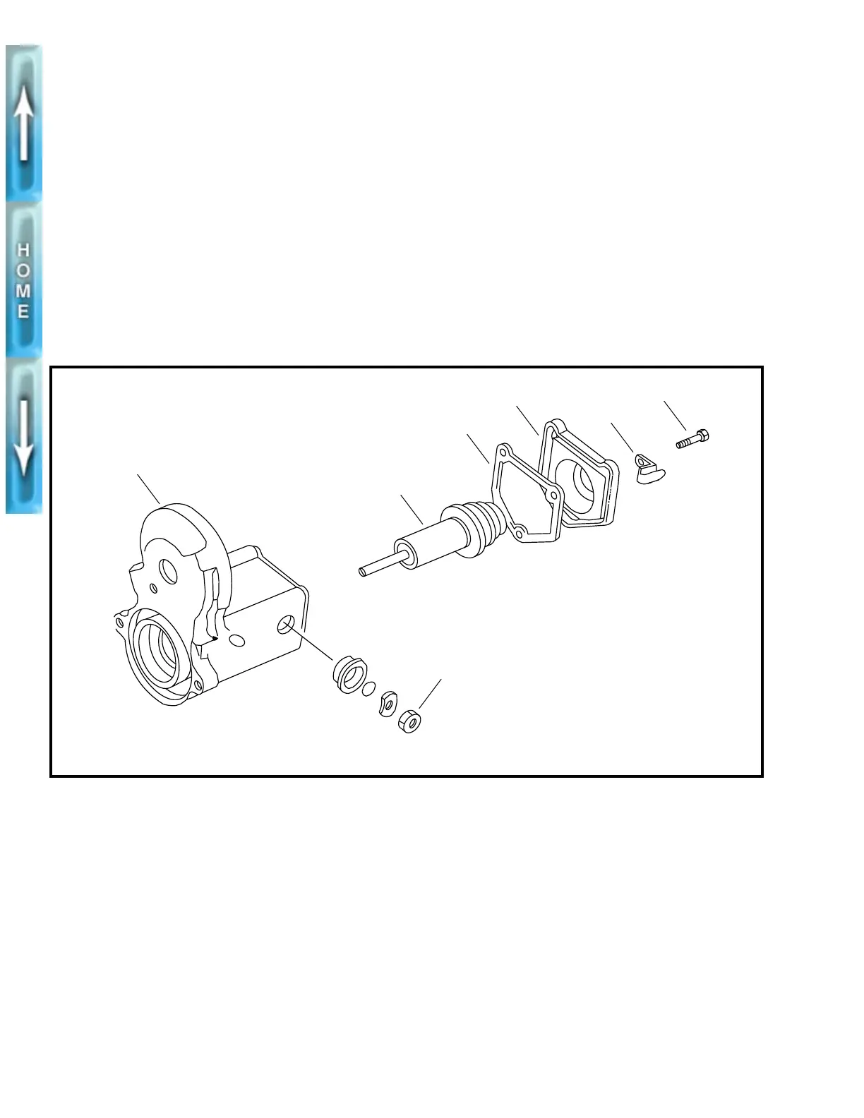
Figure 5-25. Starter Solenoid
1. Screw (3)
2. Clip
3. Cover
4. Gasket
5. Plunger
6. Solenoid housing
7. Nut
b0158x5x
1
2
3
4
5
6
1CAUTION
Do not tighten nut (7) without
removing items 1-5. Movement will
cause damage to the contact.
7

Table of Contents

Questions and Answers:

Question and Answer IconNeed help?

Do you have a question about the Buell S1 Lightning and is the answer not in the manual?

Buell S1 Lightning Specifications

General IconGeneral
Transmission5-speed
Rear BrakesSingle 230mm disc, single-piston caliper
Compression Ratio10.0:1
IgnitionElectronic
Engine TypeAir-cooled, four-stroke, 45° V-twin
Rear SuspensionShowa monoshock, adjustable preload, compression and rebound damping
Front BrakesSingle 340mm disc, 6-piston caliper
Seat Height775 mm
Bore x Stroke88.8 mm x 96.8 mm
Fuel SystemCarburetor
FrameTubular steel
TiresFront: 120/70 ZR17, Rear: 170/60 ZR17

Related product manuals