Maintenance 5-193
Installing and Configuring Processor Modules
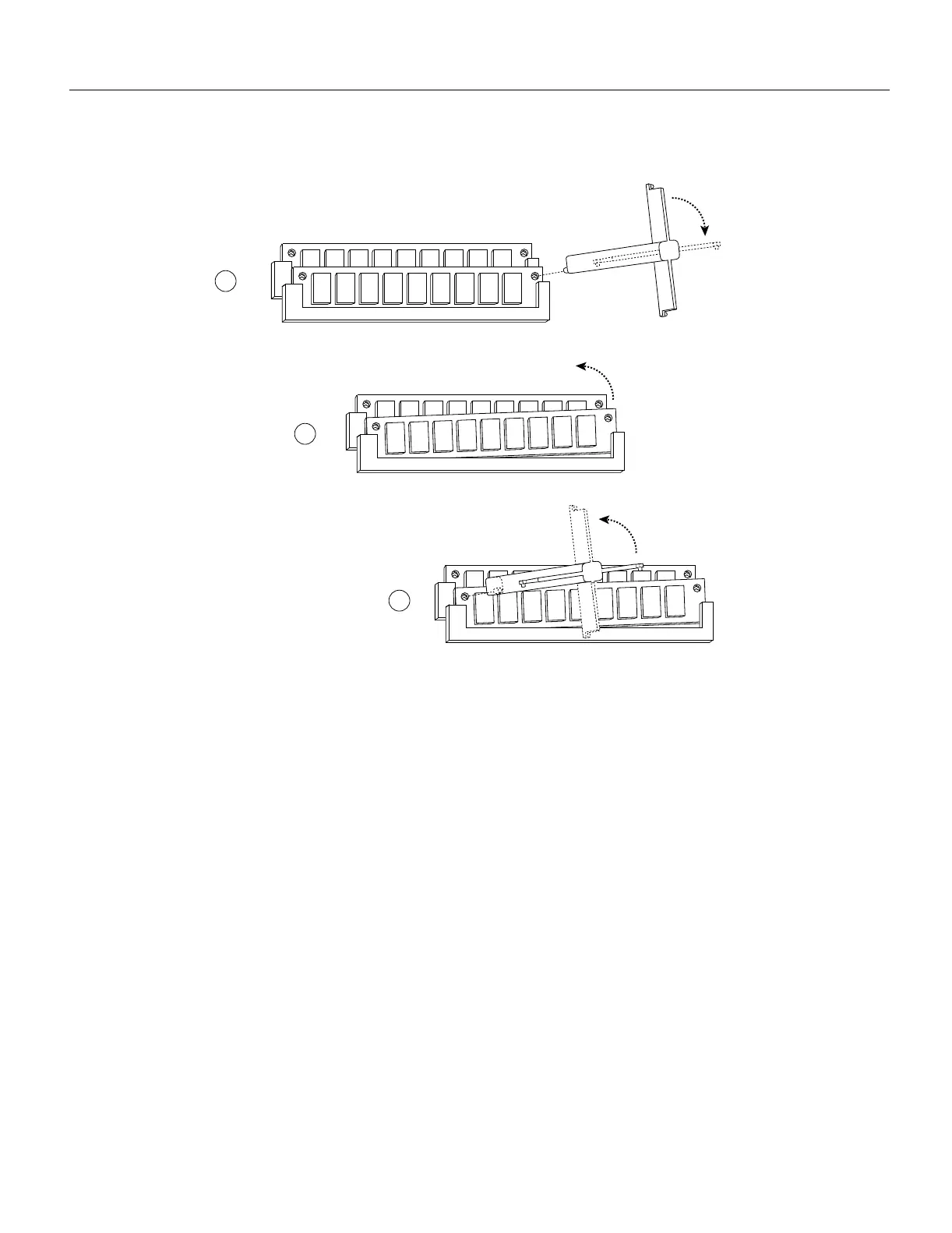
Figure 5-10 Using the SIMM Extraction Tool
Step 6
While pressing the tool downward (to keep the retainer spring depressed), rotate the tool
clockwise until the right side of the SIMM is partially released from the socket. (See
Figure 5-10b.)
Step 7 Remove the tool from the right side, and insert the embossed tip into the hole in the left side
of the same SIMM.
Step 8 While pressing the tool downward, rotate the tool counterclockwise until the left side of the
SIMM is released from the socket. (See Figure 5-10c.)
Step 9 When both ends of the SIMM are released from the socket, grasp the ends of the SIMM
with your thumb and forefinger and pull the SIMM completely out of the socket. Handle
the edges of the SIMM only; avoid touching the memory module or pins, and the metal
traces or fingers along the socket edge.
Step 10 Place the SIMM in an antistatic bag to protect it from ESD damage.
Step 11 Repeat Steps 4 through 10 for the remaining SIMMs.
This completes the SIMM removal procedure. Proceed to the next section to install the new SIMMs.
H2318
Insert extraction
tool into SIMM
socket and depress
retaining spring
Orient tool
as shown
Orient tool
as shown
a
b
c

 Loading...


