Reading LED Indicators B-273
Interface Processor LEDs
FIP LEDs
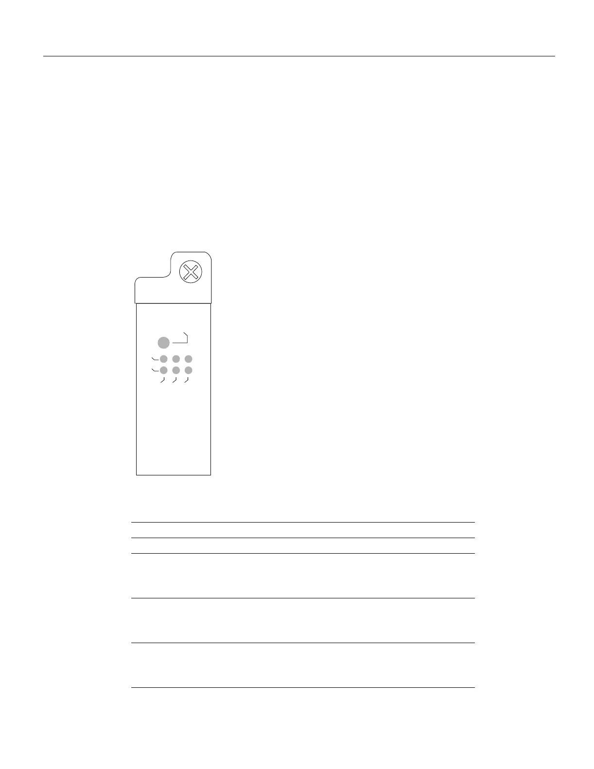
The FIP LEDs are shown in Figure B-10. The upper row of three LEDs indicates the state of Phy B,
and the lower pair indicate the state of Phy A. (The Phy B interface is located above the PhyA
interface on the face of the FIP.) As with the other interface processors, the enabled LED goes on to
indicate that the FIP is enabled for operation.
The state of each B/A pair of LEDs indicates the status of one type of three possible station
connections: dual attachment station (DAS), single attachment station (SAS), or dual homed. The
states of the FIP LED combinations, and the meanings of each, are described and illustrated in
Table B-1.
Figure B-10 FIP LEDs
Table B-1 FIP LED States—Refer to Figure B-10
LED Pattern
1
State Indication
B A DAS Both LEDs off means not connected.
– –
X X
X X
Both LEDs off Not connected
O O
X X
X X
Both LEDs on Through A
O –
X X
X X
B on and A off Wrap B
H1368a
Enabled
PHY B
PHY A
DAS
SAS
DUAL HOMED

 Loading...


